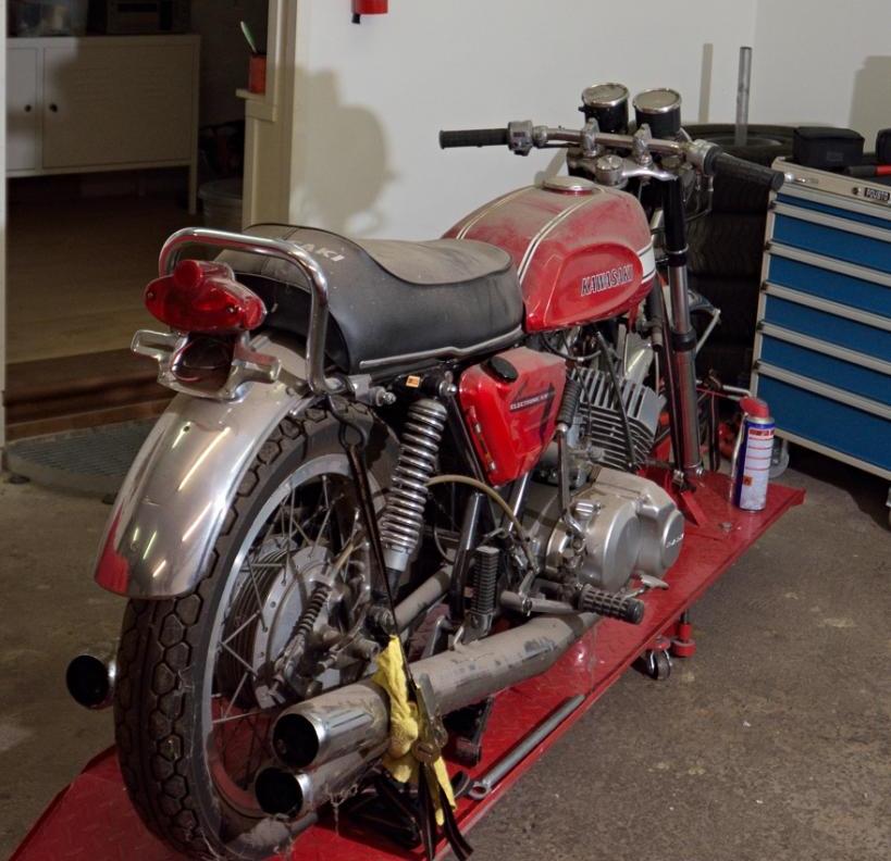
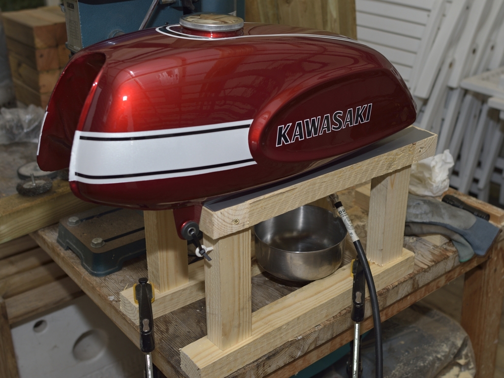
H1 ('70) Rebuild by 900SL
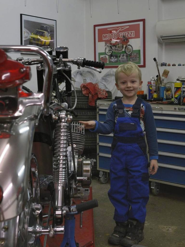
Hi everybody - I'm the new guy in class, so I'd better introduce myself:
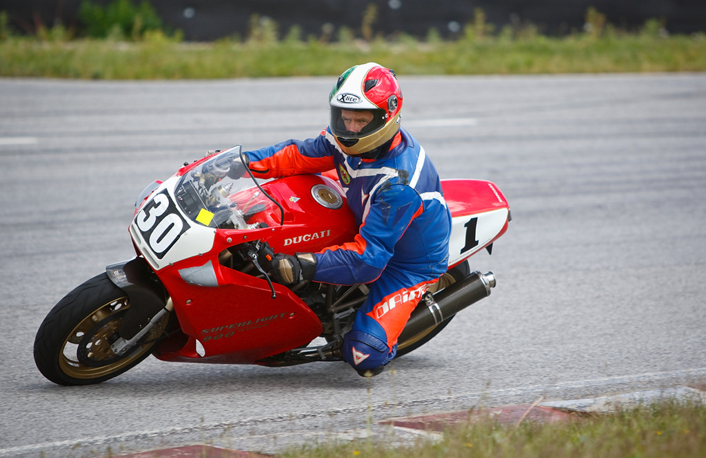
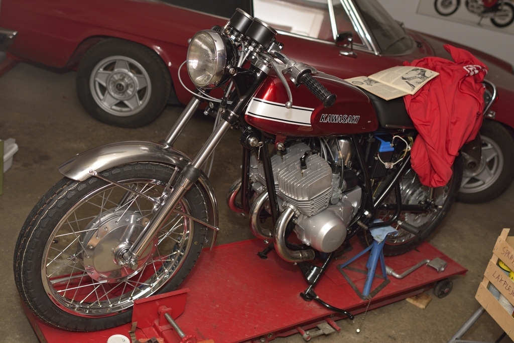
Me and my bike are located north of Copenhagen, in Denmark, Europe. Had this beauty resting in my garage since 2003.
It was a runner when I bought it, and apart from the dust, it has been preserved dry and warm:
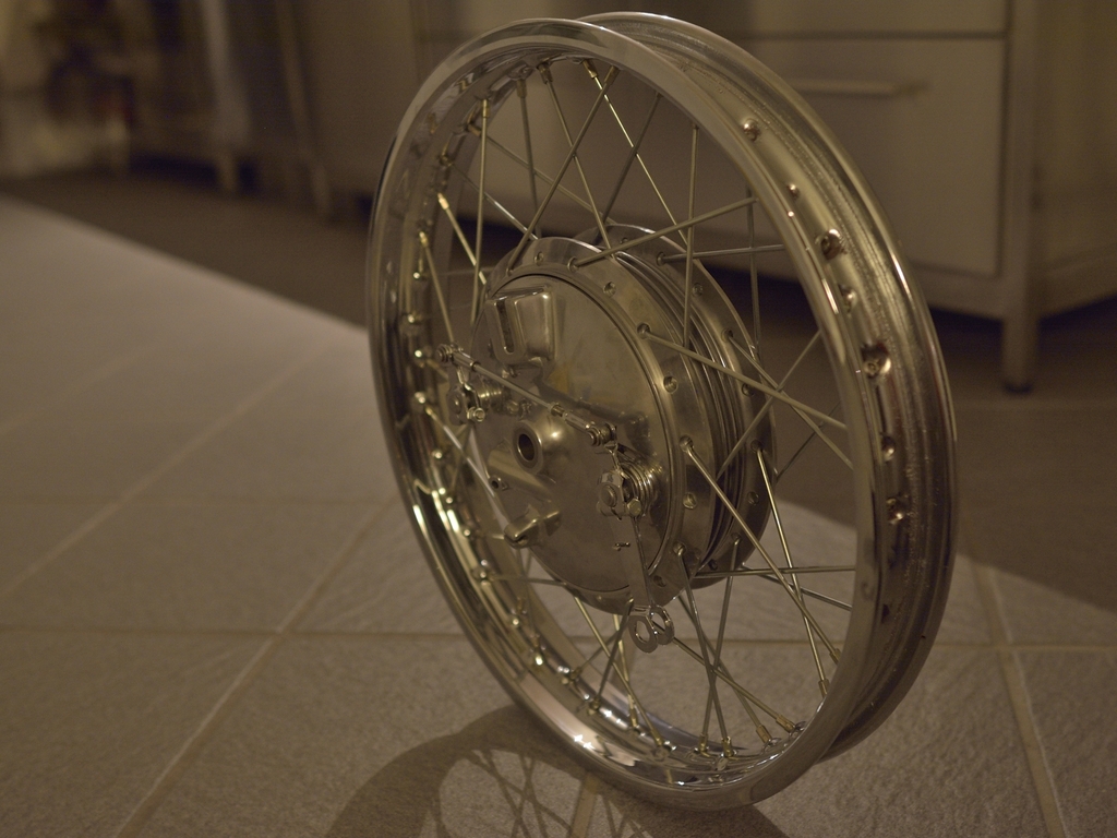
Few things were missing - and it's NOT the front wheel.
It's a 1970 with Euro specs = No CDI, instead it has 3 sets of points and 3 coils.
Frame nr. is KAF 198xx
Engine nr is KAE 515xx
In beginning of 2015, I finally began to work on it, and for some time I was not
sure, if I should just do a mechanical resto and leave the paint and chrome as original.
I finally decided to do a full resto, and that's what this is about.
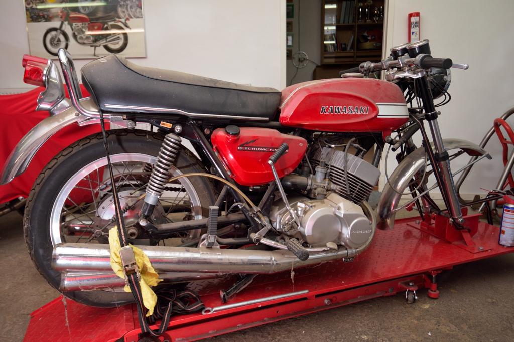
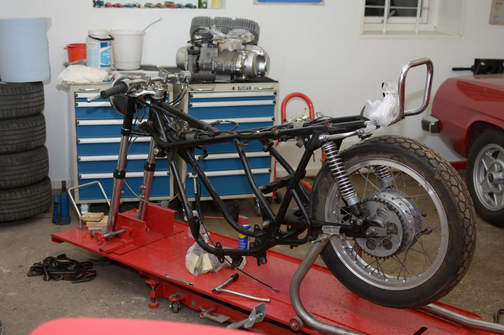
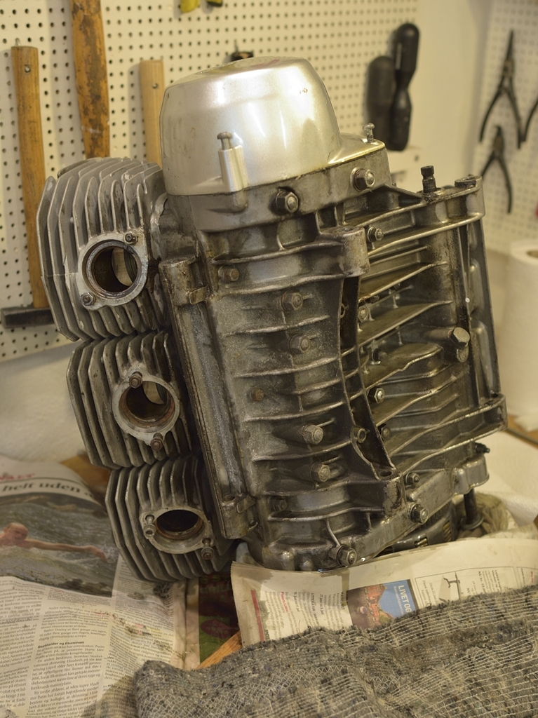
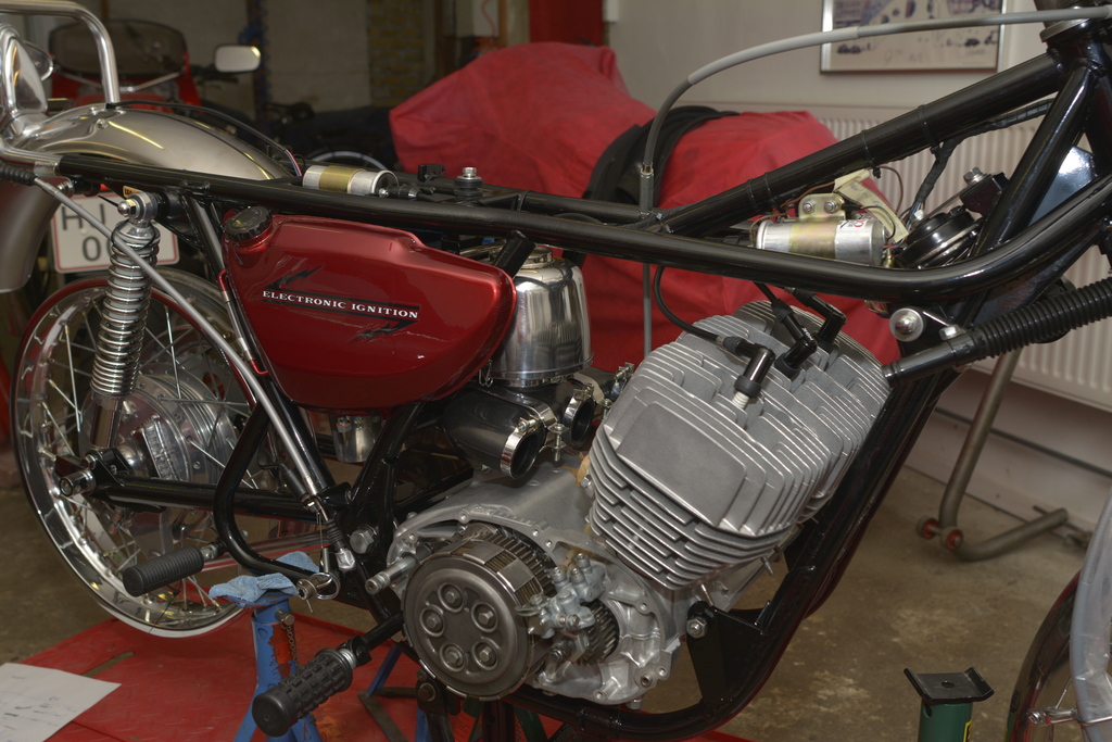
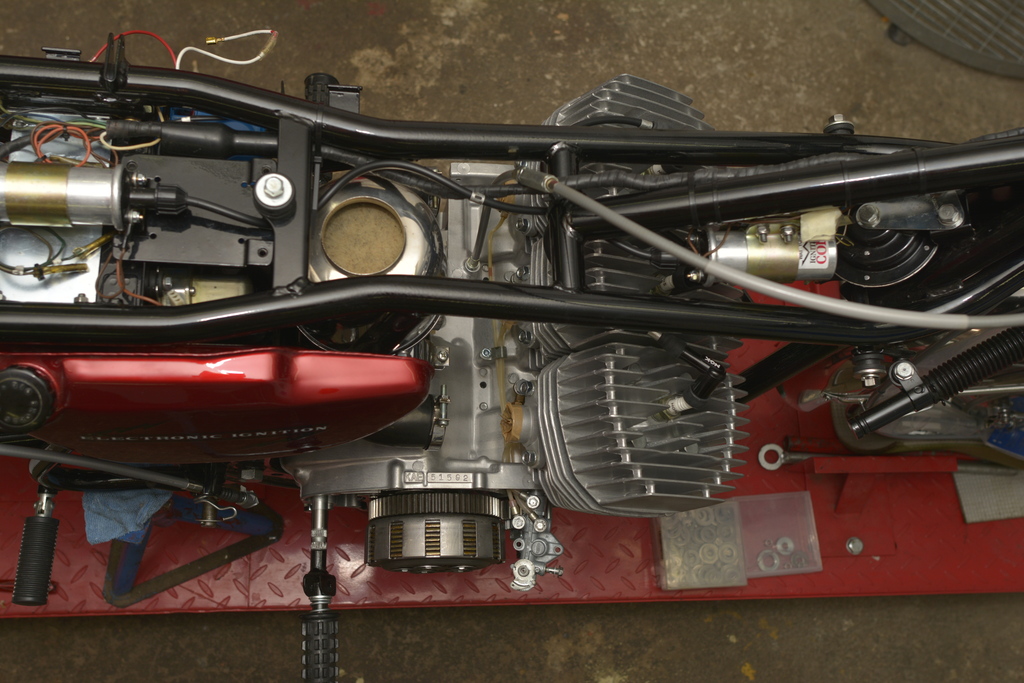
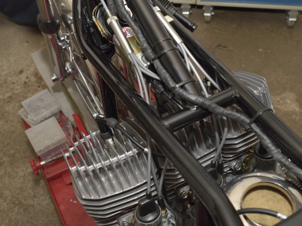
A few more pics, just to show the state it was in, when I started:
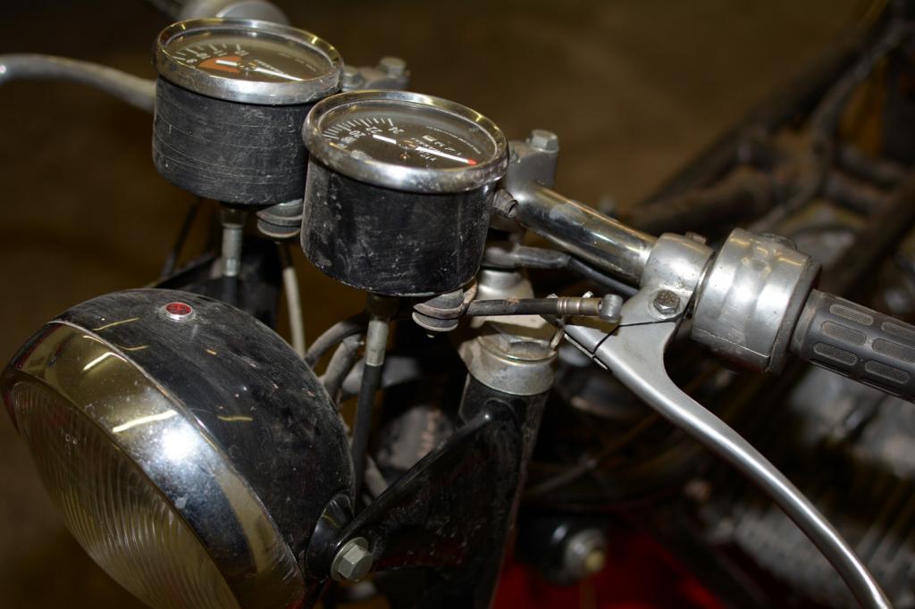
The flat bars were as they came in some European countries, at least in Denmark. Can been seen from contemporary road tests and some press photos.
To sum up:
-It was a runner, engine started easily and sounded ok, and as I remember it, the
box was OK, Front brake was horrible (won't be for long now), but maybe it's a
bit rose-tinted. 12,5 years now after all.
-Everyone will notice that the rear shocks are Hagon, rear rim a non-original,
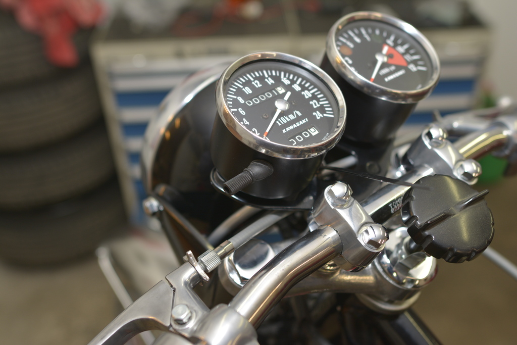
but nice Borrani. Rear footrest are non original. I missed that the Tacho was
from a 250 S1 or maybe an A7.
-The original mechanical steering damper are missing and so are the steering
lock.
-Exhaust pipes are nice, no scratches or dents and chrome is good, as the rest of
chrome in general.
-Original fenders in very good condition, original paintwork, chainguard, airbox,
levers and so on.
-Some history was known.
-Kick start lever has been replaced with one from a H2 on these pics.
-Seat has been re-conditioned.
Let's start to take it apart, and see what shows up ...
I'm not professional, and being my first Kawa resto, I played safe and took a lot of pictures. I dismantled the bike in larger units only, and wrote down a lot of info:
I managed to salvage the original ISO sticker, peeling it of with an old-fashioned razor-blade:
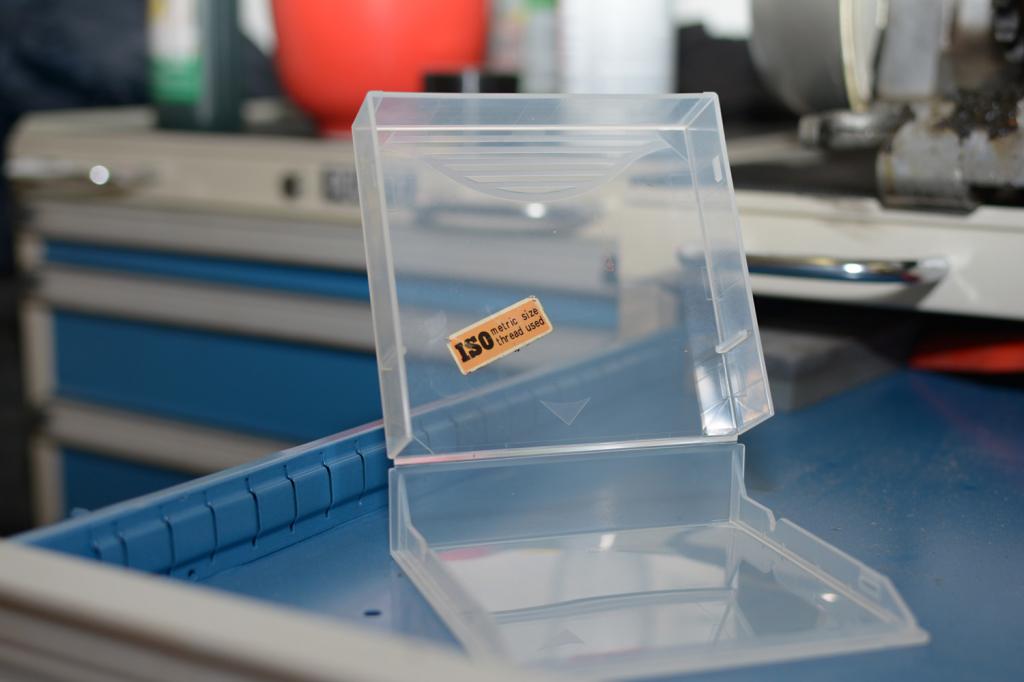
but, of course I also managed to cut my finger!
Hope I will be able to re-apply it when the frame is back from the painter.
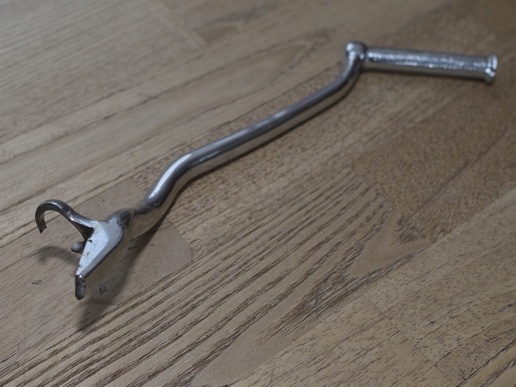
Then I went out and bought this piece of kit:
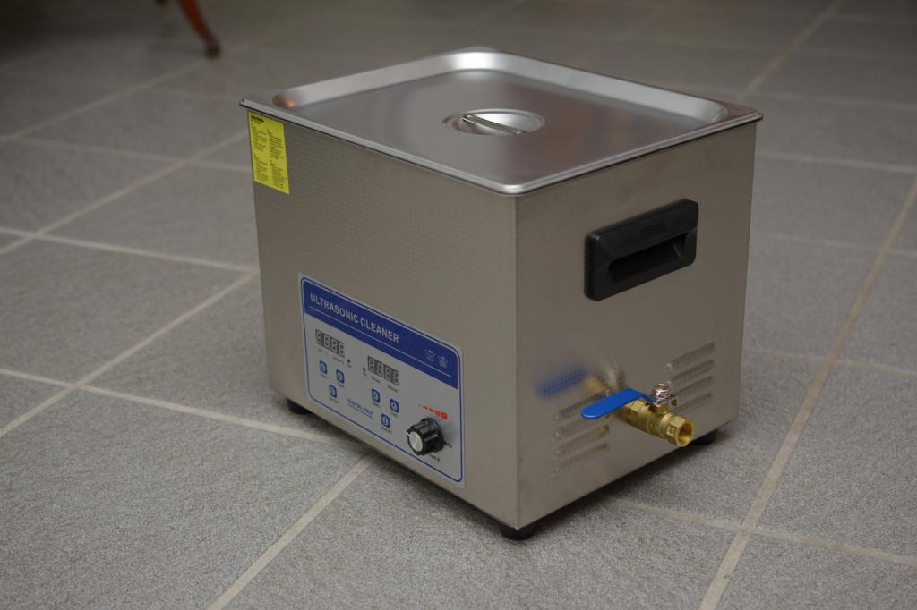
Capacity 10 litres and a build-in heater
OK - next chapter:
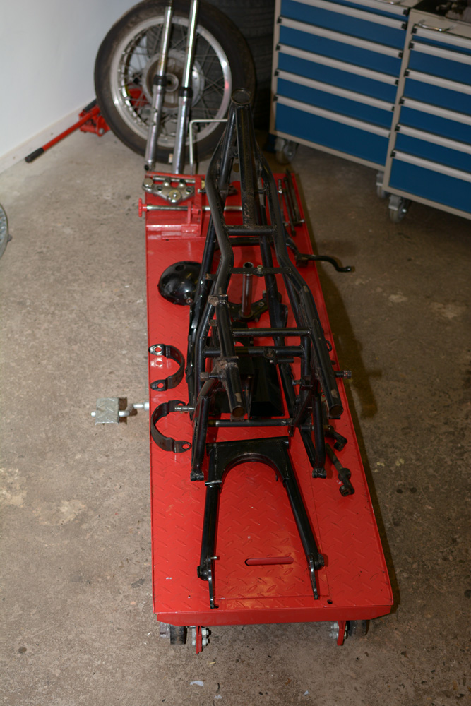
Frame + parts are back from blasting and painting.
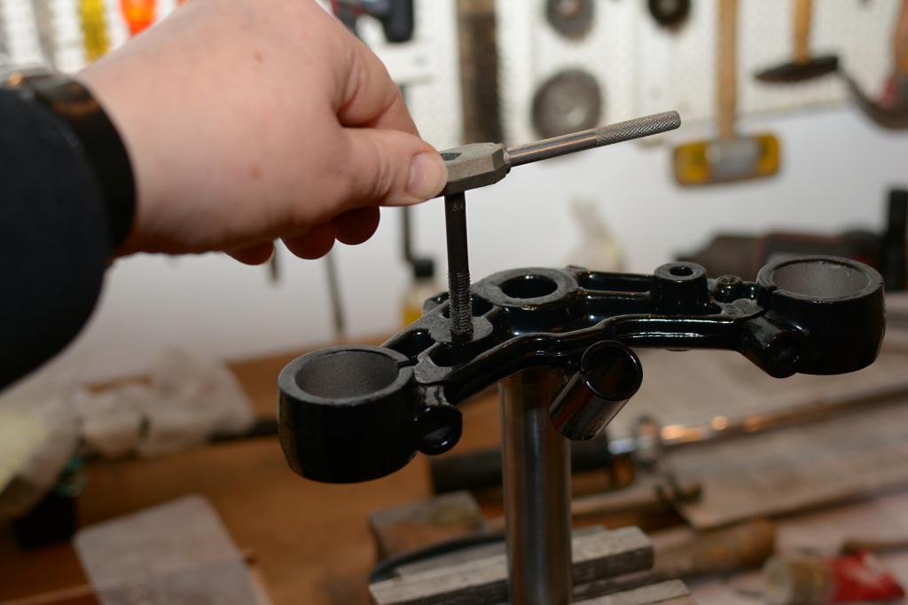
Of course all threads was masked before blasting, but I do refresh them anyway,
as I have the tools and it takes me 5 minutes:
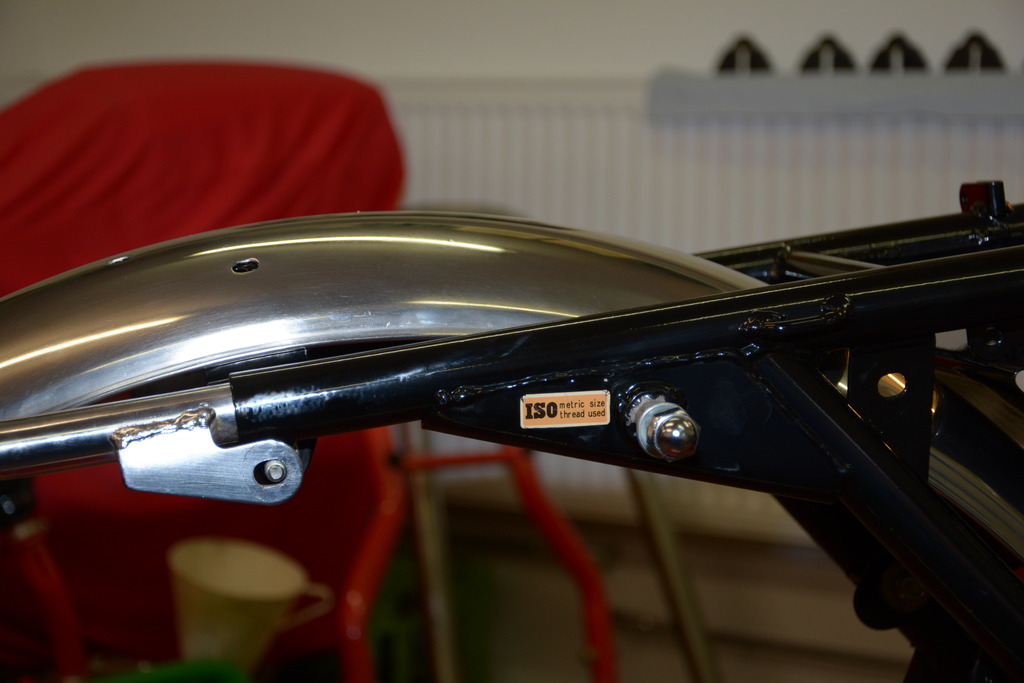
I also re-apply the original ISO sticker which almost cost me my thumb! I
apply a coat of clear on top of the sticker, to protect it.
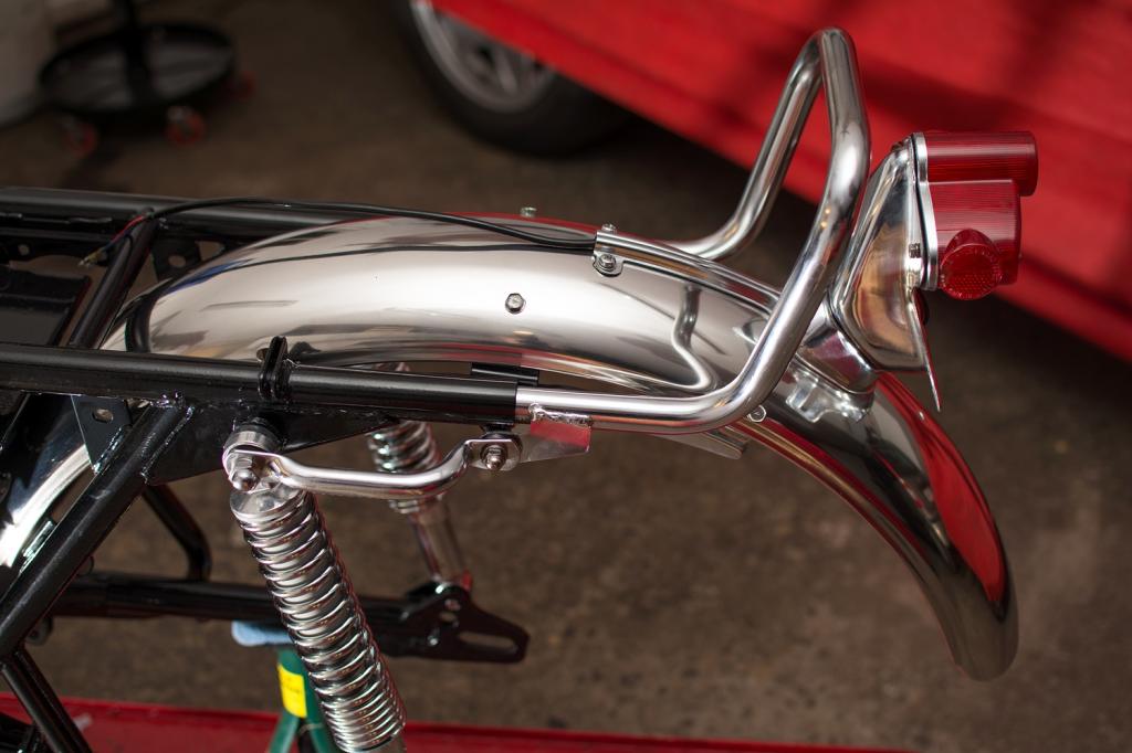
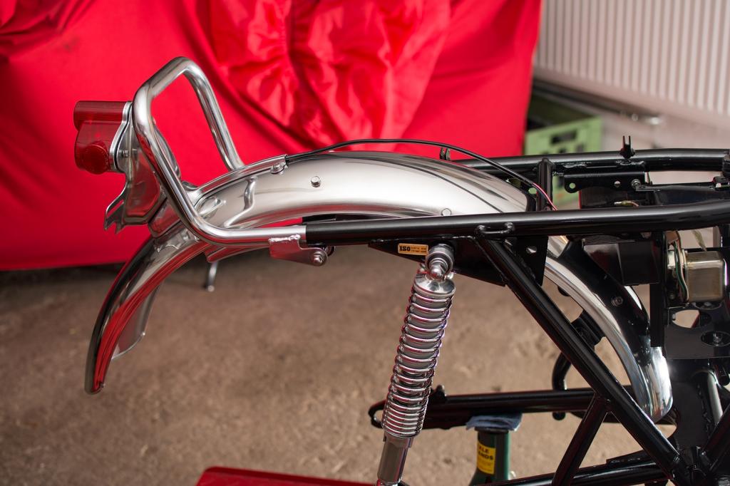
The rear fender is mounted too, it just needed to be polished (stainless stuff,
I think)
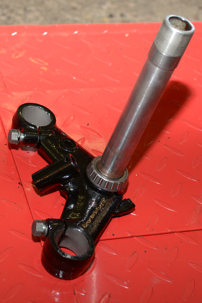
I deviate slightly from the "everything to-be 100% original" theme, as I use tapered roller bearings instead of the original:
Some words about my approach to this resto:
The bike had a lot of original parts which have been on this particular bike since new, and I intend to keep as many of these as possible. This includes repair, if possible.
If repair is not possible, I will try to source original parts. If not available, or ridiculously expensive - like >200USD for a an original flasher
relay with the mount - I will use repro parts.
I'm aiming for a bike in nice, as-original-as-possible, condition, with all mechanical parts in top condition, as I intend to ride it, at least to some extent.
As I said, it's my first Kawa resto, and I'm not a proff. so guys please:
If you see that I'm heading in the wrong direction, or I'm about to make a
stupid move (this will happen for sure don't be polite, but chime in - I can take it!
As I had no access to tools which can press in the roller-bearing race, I had to rely on the old trick:
I borrowed a little space in the wife's freezer, threw in the races and gently
heated up the steering head pipe to approx. 40-50 degrees celsius.
The race will shrink a little, and the steering head pipe will expand a little.
Enough to make you fit the race with only some gentle blows from a mallet.
Of course you must not hit the revolving part of the bearing. Only hit the race,
and to do this carefully, you must hit the top egde with something which has
almost the exact same diameter - like the old race, or a socket from a socket wrench set:
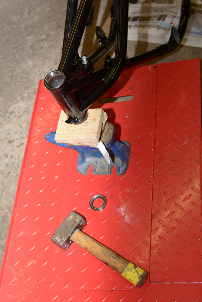
Job done:
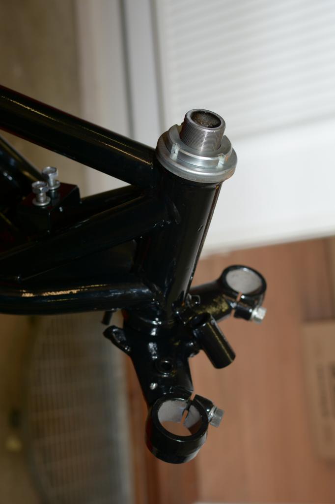
Somewhat later:
Front and rear fender are Stainless (in contradiction to Honda for instance)...
... and they were very nice, so it was an easy job to clean and polish them. I
sanded the downside and applied 2-3 coats of silver.
Nylon lock nuts are of course not original spec., but I don't wanna tighten nuts
on some dark secondary road.
Shocks are repro's from Diablo Cycles, but grip, rear fender stay, license plate bracket and tail lamp are the original ones, and hasn't even been rechromed:
Starting to look a LITTLE like something:
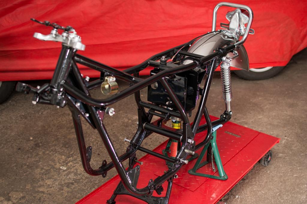
- notice the correct Kawasaki bolts!
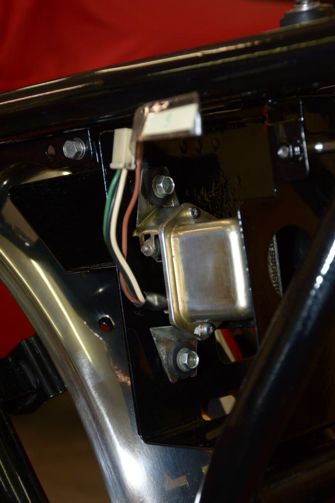
Original Mitsubishi voltage regulator in nice condition with original wires. Just cleaned and polished a bit by hand:
Battery box:
The first parts starts arriving (this will continue for a looong time, I'm afraid):

A French guy (Patrick Bras) makes some nice bolts and fasteners:
The mechanical steering damper which came with the bike, was not the original
type, and I searched for long for an original replacement.
I finally bought one from from Sweden, but it was slightly damaged, so I had to think out a way of fixing it:

Sacrificing the wrong steering damper (made of the same material) I fabricated some grain:
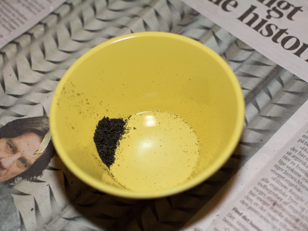
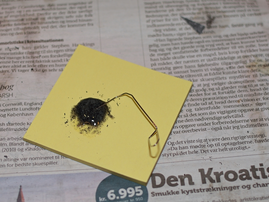
The grain was mixed with two-component Epoxy glue and applied to the right stering damper wheel. I just had to make a stop, preventing the glue from slipping down:

The finished damper, with all parts:
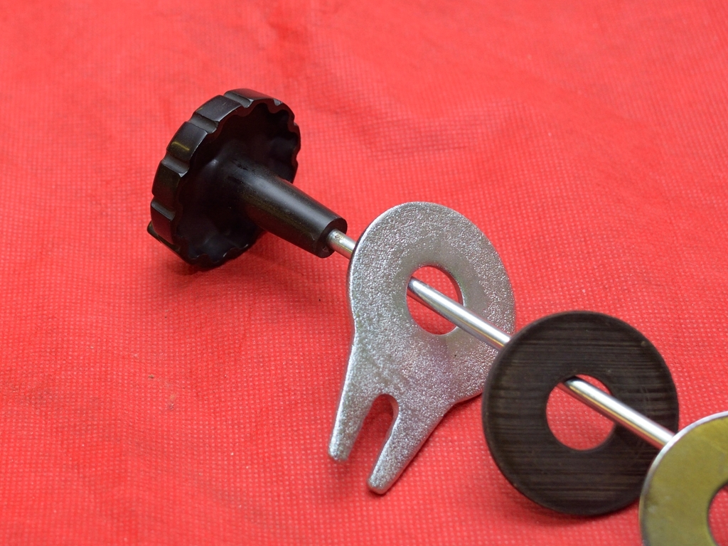
Finished - (cotter pin is missing):
Had to source a new steering lock (NOS) as this was missing too. These parts are not exactly cheap!
OK folks, let's take it another step forward:
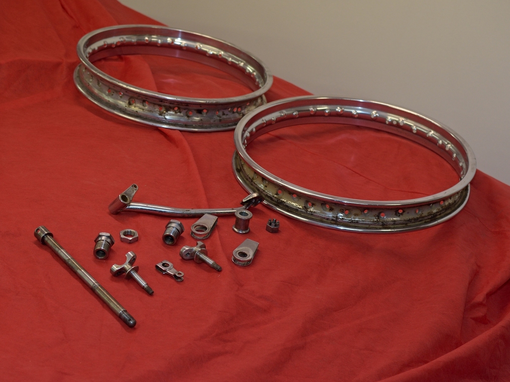
I had to source an original Takasago rear rim instead of the (very nice) Borrani
alloy. I managed to find one in Sweden, just hour in car from where I live (
yes, you guessed it, there a bridge btw. Denmark and Sweden).
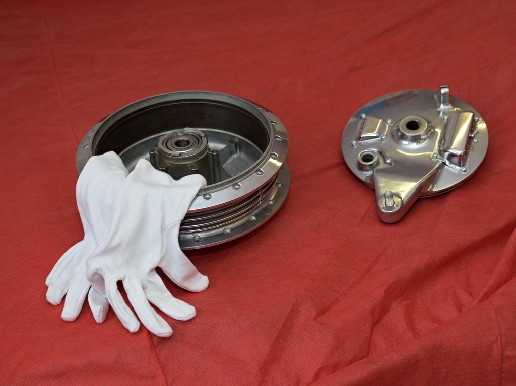
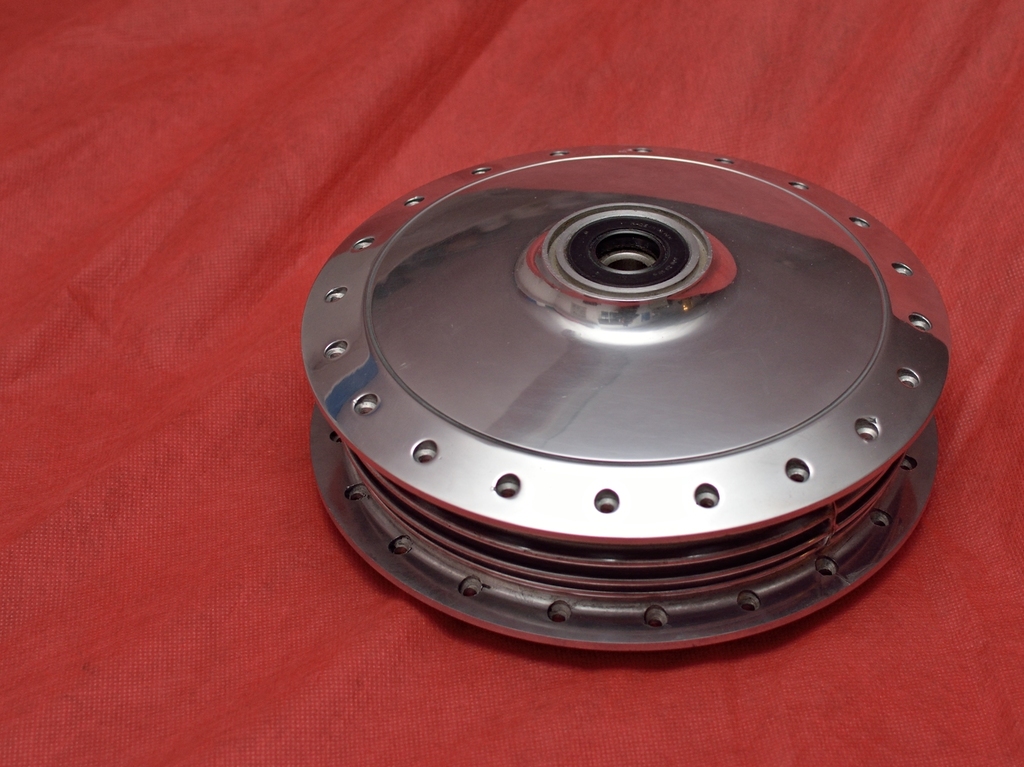
As a bonus it got a complete rear wheel, meaning that I now had surplus brake drum, meaning 2 to choose from.
I chose the best of course, and after a little spit n' polishing:
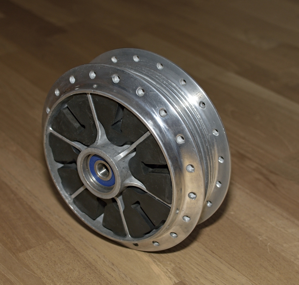
The hub for the rear sprocket:
I just LOVE the vent on the rear brake:
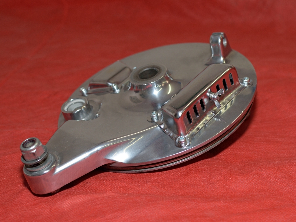
... anyone ever wondered why the rear - and not the front brake is vented ?
With 2 rims, and a lot of other parts ready, I could send the first batch away for re-chrome:
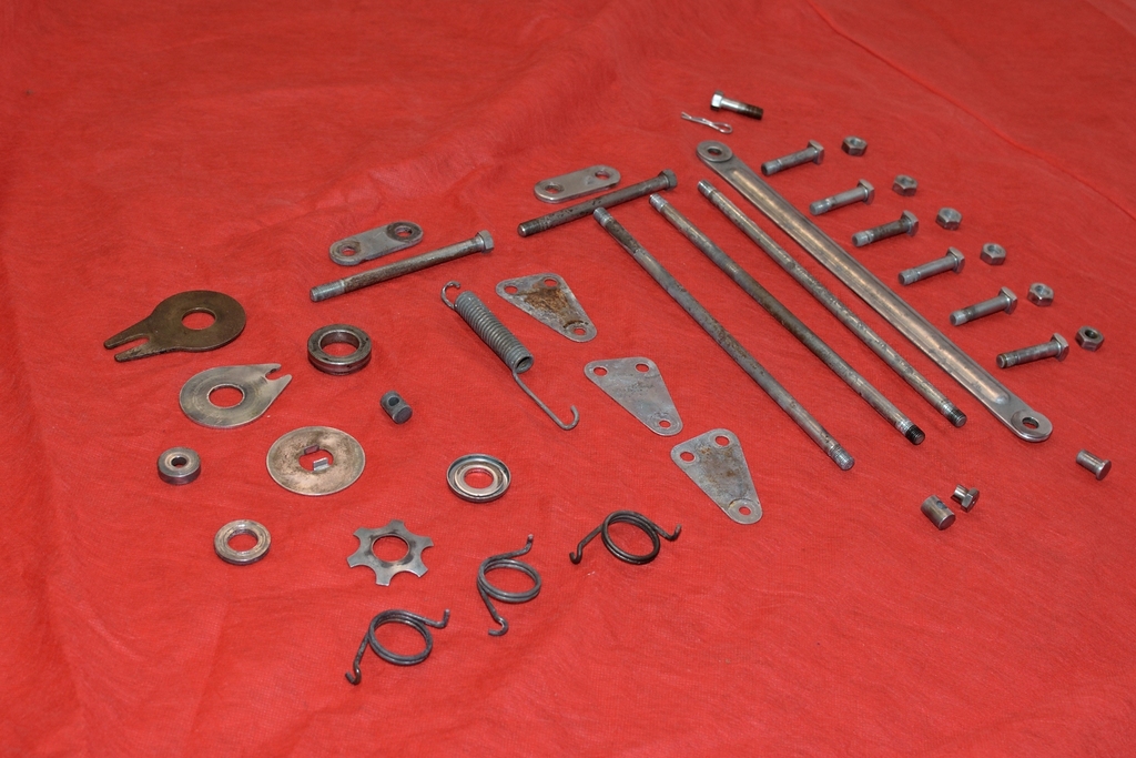
Some of the parts to be zinc plated:
Summer's almost gone, and while I'm still waiting for last parts to return from re-chrome (he does a good job) it's time to give the front fork some attention:
Thanks to a fellow member at the Swedish triples forum, my attention was drawn to Ralf Gille in Germany, who offers these fine bushes:
With bushes from Ralf and new tubes bought from Diablo Cycles, we have almost
everything it takes to rebuild the front fork.
The fork is a very simple design. Kawasaki made some marketing pitch and labeled them as "Ceriani-type" but to me they seem very similar to older English forks, like the ones from 1950-ies Nortons.
The forks are easily dismantled, but take care when you unscrew the top of the
fork-legs (where the seals are located) If you have no better tool but a big wrench, these parts are easily scratched.
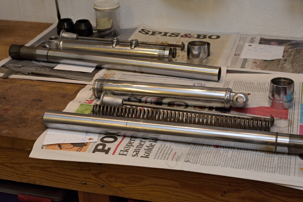
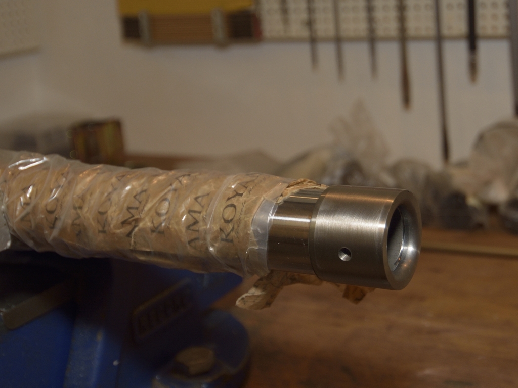
Here are the old forks dismantled - pretty simple stuff, yeah:
Here are the new tubes as they came from Diablo Cycles:
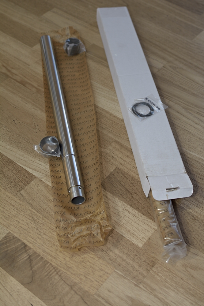
As you can see the top bushes comes along, but not the bottom ones - which I had
to buy from Ralf.
It's of course essential to clean the parts to be reused, especially the outer/bottom tubes can be a little tricky to clean. I used a stiff brush on a long
stick, like the ones used for bottles.
After cleaning of the outer tubes, they were send away for re-chrome, and while waiting, I started working on the inner tubes...
... the old inner tube are seen here:
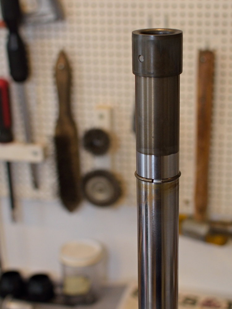
Note the dark colour at bottom end of tube (picture shows tube upside-down) which indicates where the oil level was, and that it has been standing still for many years.
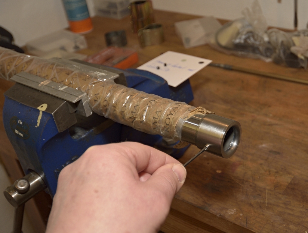
Inner tubes are tapered where the bush sits and there is a thin shim which must
be reused on the new tubes, and so must the stop ring, which fits in a machined
slot on the inner tube.
Maybe it's easy to see on next picture:
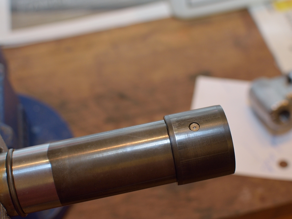
Therefore we need to drill out the 2 "rivets" which holds the lower bushes in place:
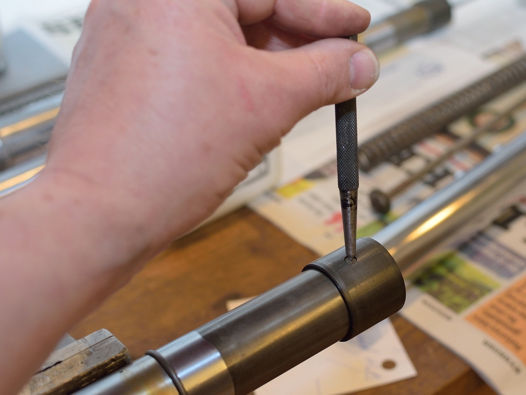
Here I punch a mark, so I can place the drill in center. No big deal here, as neither the bush nor the inner tube are reused, but you can just as well pratice doing it right. My 2 cents.
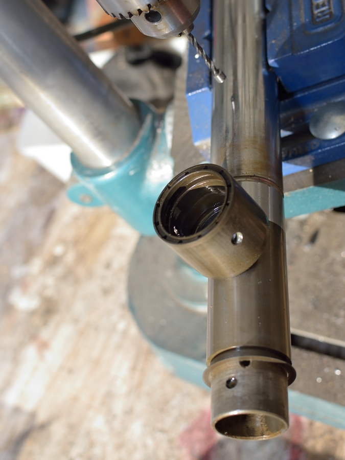
A vertical drill makes it an easy task:

Loose:
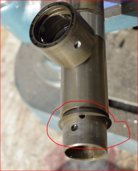
This was the easy part!
Now we need to remove the 2 stop rings from their groove in the inner tube.
The rings are pretty stiff and made of spring-steel, but it can be managed, and you
can slide them the short way down the inner tube You need to reuse these 2 on
the new tubes...
Just to recap - It's import that you preserve these 2 washers for the new tubes:
same goes for the stop rings:
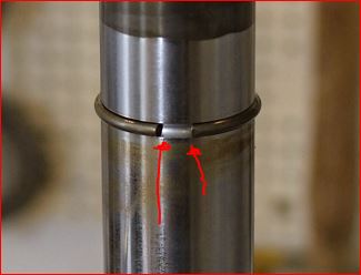
A couple of notes about the stop rings:
(1) You have to overcome the spring force by inserting a pair of suitable pliers,
and then slide the stop on the tube surface.
This will for sure leave two scrathes on the surfaceof the tube. No big deal, if
you plan bin the old tubes, but otherwise take care and do apply some tape on
the tubes to avoid the scratches.
This is even MORE important when you re-apply
the stop rings onto the new tubes!!
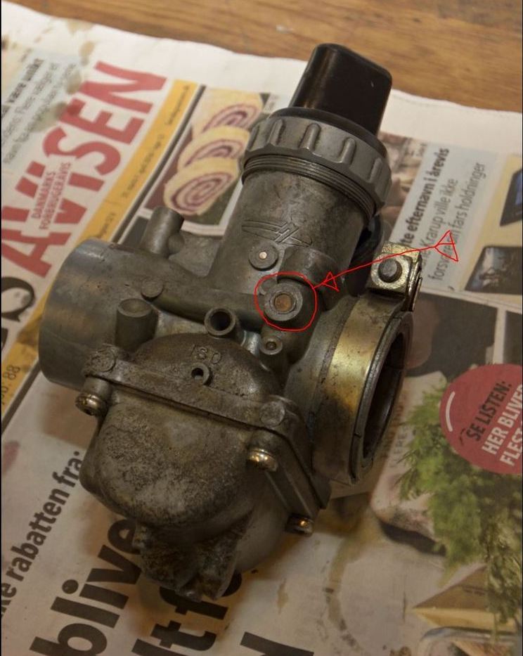
(2) When removed, you will probably see or feel, that the gap ends of the stop rings
are pretty sharp (see picture with 2 red arrows) and not chamfered in any way -
at least mine were not.
I strongly advise you to chamfer the gaps a bit, before you re-apply the rings.
I managed to do this with an ordinary coarse file.
After chamfering the gap ends, I practiced re-applying them on the OLD tubes,
until I was sure I could manage without scratching the tube surface.
At last, I applied some tape to the tubes to cover the distance the stop rings
have to travel when applied on the new tubes.
Sorry, but I don't have any pics on these 2 particular tasks. No rocket science here, just take your time and work in an unrushed manner.
With the stop rings re-applied onto the the new tubes, we can go on with the new bushes...
The lower bushes comes with pre drilled holes and 4 mm countersunk unbraco screws, remember:

The screws are made pointed at the end touching the inner tube, as if they can just be tightened and press againts the inner tube, but I took the decision to drill a hole through the inner tube and to cut a thread all the way through but bushes and inner tube - see below:
... and by the way, don't expect the pre-drilled holes in new bushes to match with the ones in the tubes, as they come from different vendors.
When you finally assemble, remember that bushes must be mounted with small oil escape holes facing the top of the fork and facing the small shim carried over from old tube:
Last step is to screw in the small unbraco screws. I applied a drop of LockTite (the red one) Better safe than sorry.
Inner tubes are now finished, and ready to be mounted into outer tube, which are back from re-croming, very convenient.
Obviously, the right amount of oil must be added (I use factory specs + 5%) This makes the damping a bit firmer, but don't overdo it, as too much oil will put more pressure on the oil seals (which are new of course).
The top bushes comes with the new inner tubes from Diablo Cycles, and it's pretty straightforward to assemble the bits:
Top bushes can be seen pointing out on the fork legs nearest camera.
Almost there:
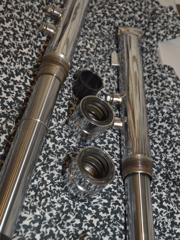
The new oil seals must of course be pressed into the outer tube nut before the
nut is mounted.
The presence of the oil seal will add to the resistance when
tightening the outer tube nut which has just been re-chromed, and we don't
wanna spoil the chrome, so I advise you to clean the thread carefully - both
inner - and outer, and then apply some oil to the thread.
I wrapped some layers of thick rubber tube around the outer tube nut when tightening, and I only worked on the top end of the tube nut, because this end will be covered by the big rubber dust shield.
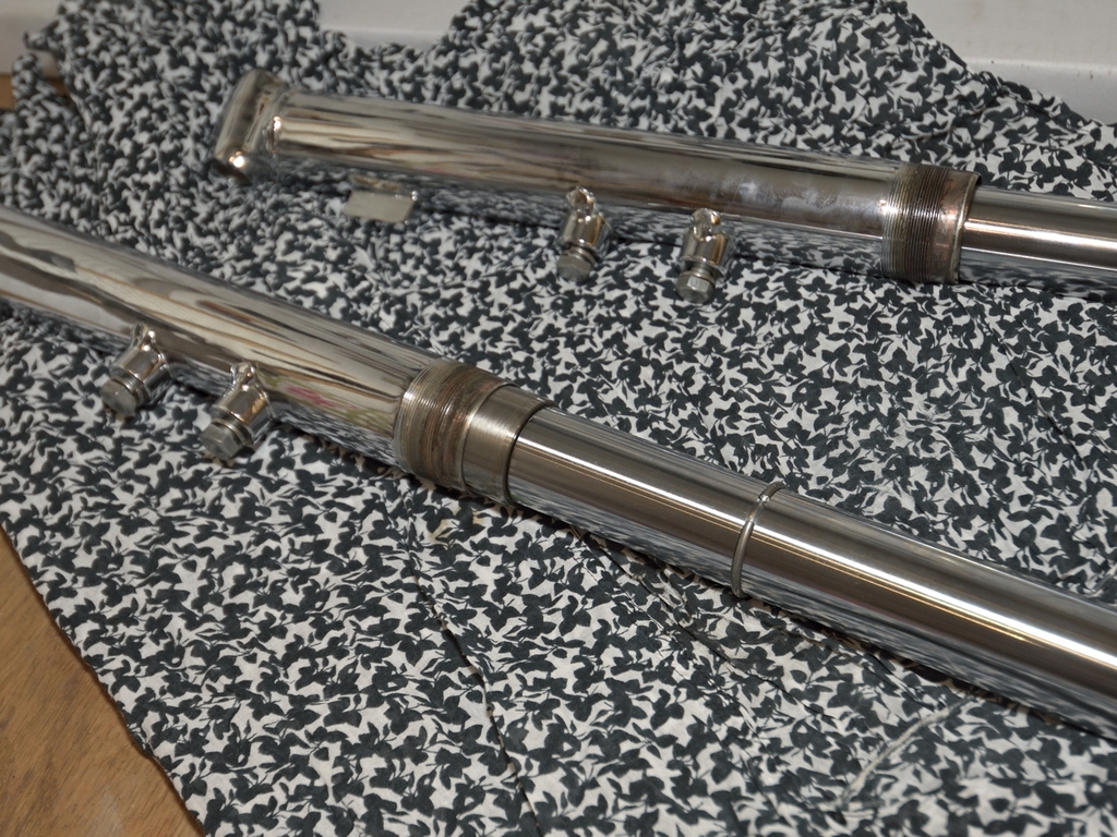
Looking sharp - right ?
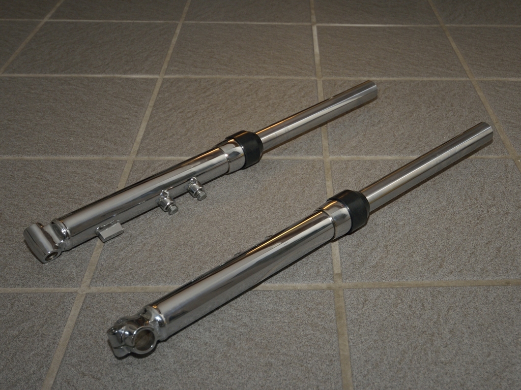
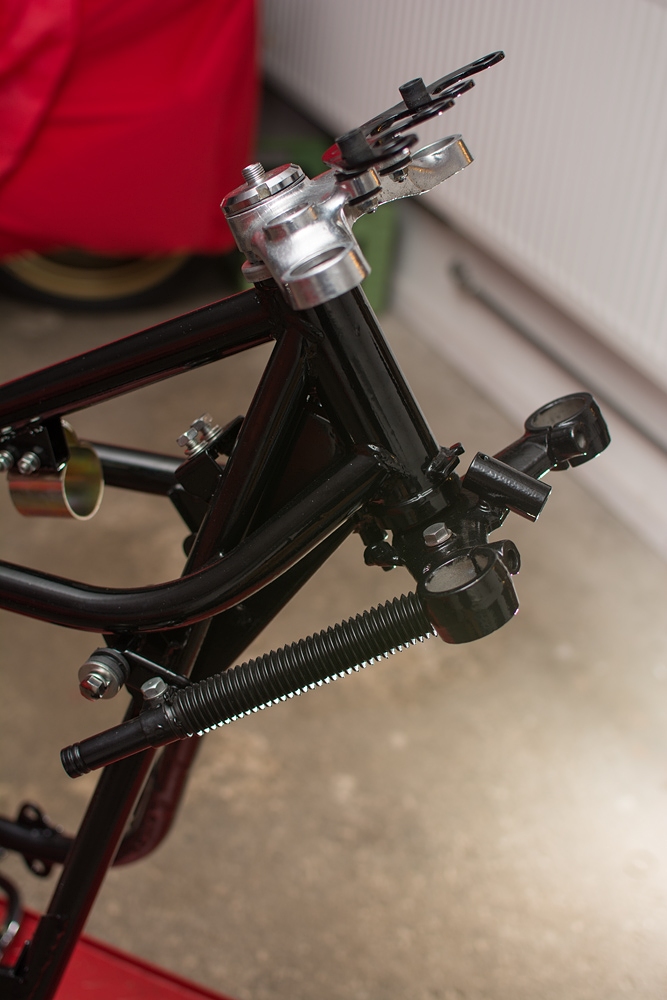
Well those fork tubes should not remain lying on that floor for too long, better get them mounted:

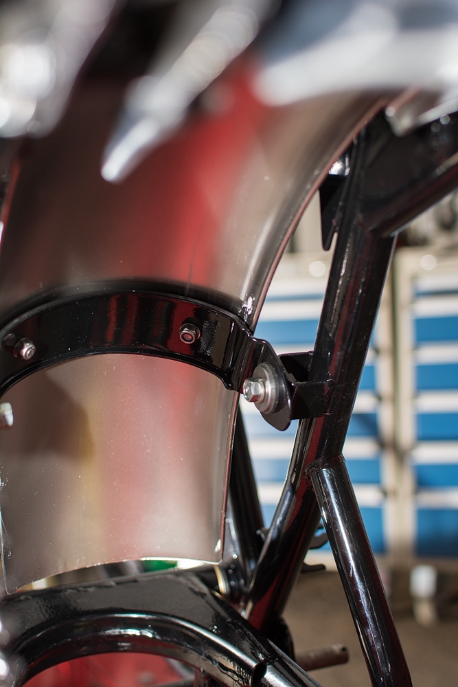
And this is how it looks when tubes and fender in place:
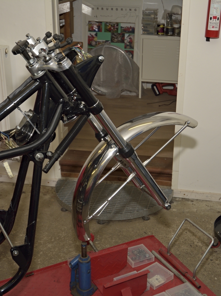
Front fender was in very good original condition, some gentle polishing with a rotating polishing wheel did the trick. The flip side was sanded down and some layers of silver coat was applied. Again, I deviate from the 100% originality thing, as I use Nyloc muttors instead of ordinary ones + spring washers, which I think is hopeless. I intend to drive the bike when finished, at least on Sundays and besides, you can't tell when looking from the outside.
The black fork covers / ears were in fact in such good condition, so they weren't even repainted.But as I use tapered roller bearings instead of the originals (which looks as something from a child's bicycle), you have to shim the ears, as porschedave also mentioned earlier in this thread.
The fork top bolts were rechromed, and all rubber /seals were renewed.I had to buy a new lock cylinder complete with keys (not cheap) as it was missing when I bought the bike. I can almost guess why.
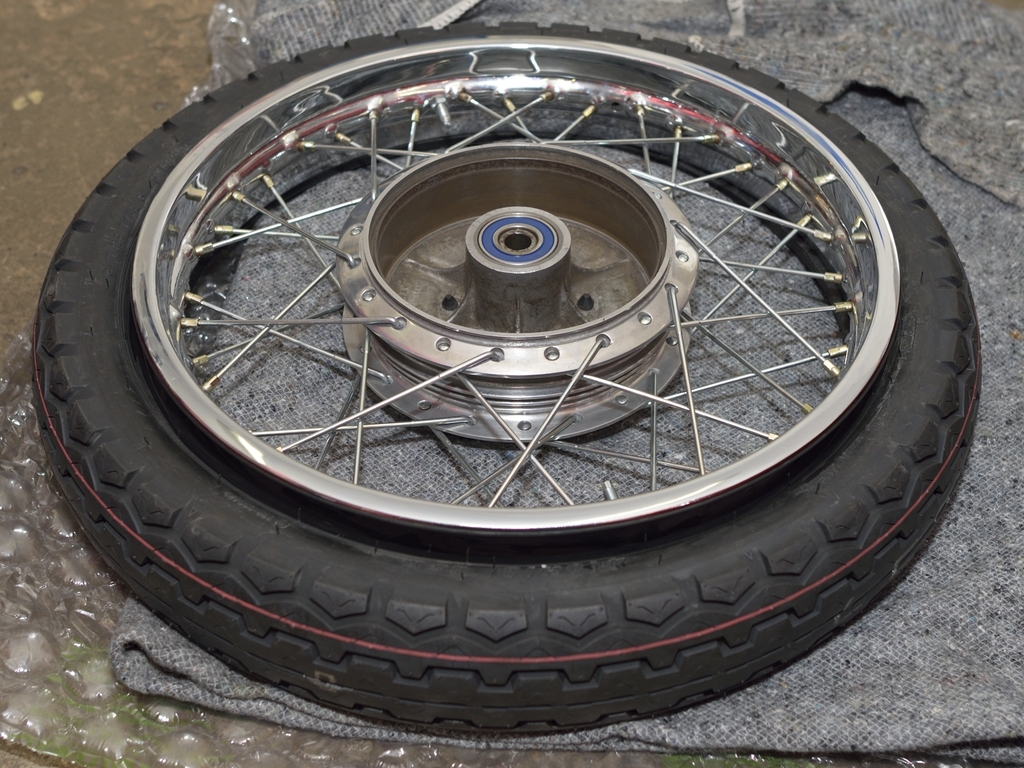
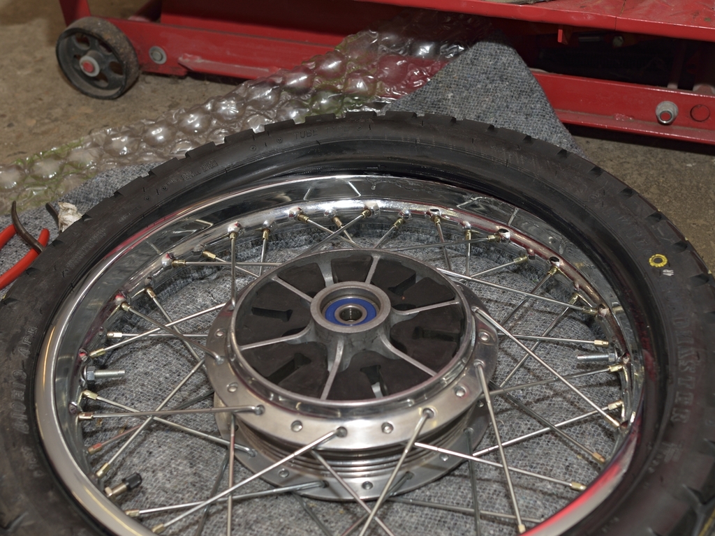
Better get started rebuilding those wheels, stay tuned ...
I did not shoot that many pics when I rebuild my wheels (I simply forgot) Also there’s a lot of articles about this topic in bike magazines and loads of videos on YouTube for instance, so I will not dwell deeply into the technics, but instead share some notes and tricks which helped me.
If you scroll back to some of my first pics, you will see that the rear rim is some Borrani alloy rim, which was very nice, but not original. I still have it, if someone is interested…The front rim however was the original Takasako rim. I managed to get hold on a complete rear wheel in my neighbor country Sweden. There are many more dedicated Kawa enthusiast in Sweden, than in Denmark, The even have a club, with a very active discussion forum http://www.classickawasaki.se ... but I guess you will not be able to understand much of it.
With 2 used, but good rims, it was just a matter of handing them over to the chrome shop and wait forever. In the meantime you can start saving up a few bucks, cause cheap it aint! Anyway, he did a nice job as always.
Before you take the wheels apart, do remember to:
- Take some pics which will show you the pattern of the spokes and how they are
laced.
- Keep a least one outer and one inner spoke from both wheels. This will make it
easier to ensure that your new ones are right.
Like this:
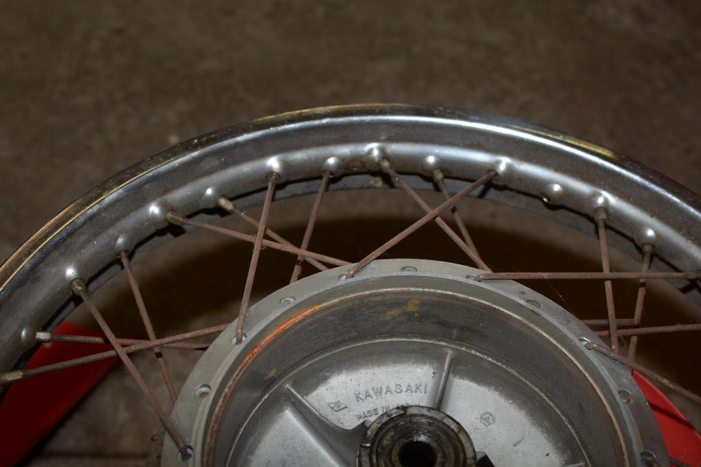
Before-image of wheel
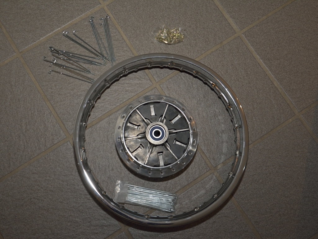
I use mild steel spokes for my rebuild. In the beginning I was biased towards stainless, but I ended up using mild steel. Can’t remember why. Of course it was not stainless back in the 70ties, but as I remember it, I read something not in favour of stainless – are they too brittle? Anyway I got a nice set of spokes and nipples from Ralf Gille in Germany.
Here we are ready to start lacing a rear wheel:
Some time later:
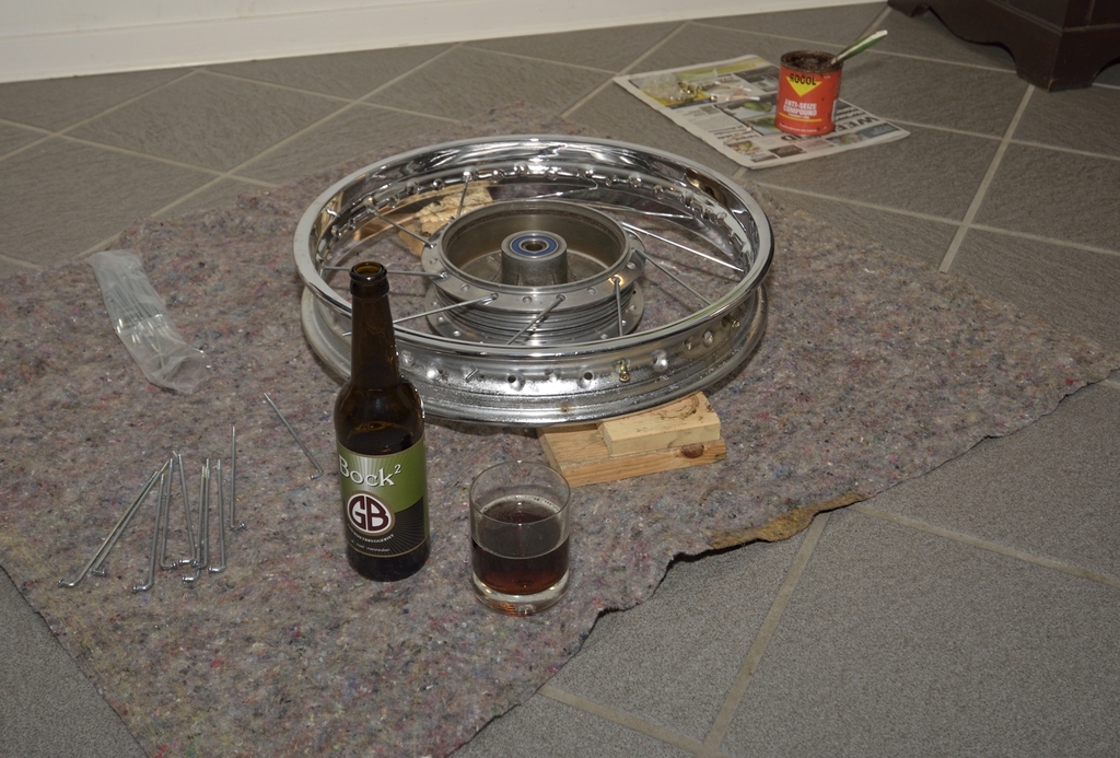
Half of the spokes are laced, and I've already started celebrating with a good Danish brewed Bock beer. I'm more of an IPA guy, but...
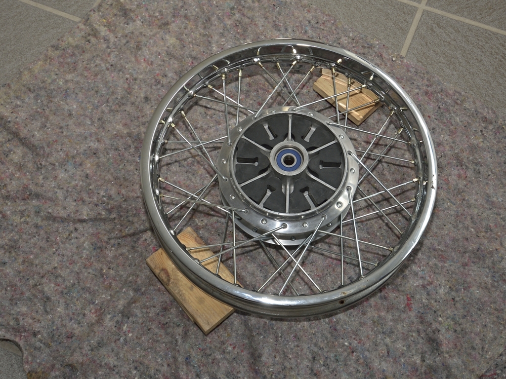
A little later and some more beer, we have a nicely laced rear wheel:
Time for some Do's and Don'ts:
Do
- apply some copper grease to the tread before on-screwing the nipple.
Spokes are mild steel and nipples are most likely some Brass alloy, so over time
these will corrode a bit
- get yourself a decent spoke wrench, it cost a few bucks
- tighten all spokes lightly but evenly when finished lacing
Don't
- Use an ordinary wrench for the nipples. Either it's too large or has too many
sharp edges, which can scratch you lovely new chromed rims
- Necessarily buy a fancy jig for trueing wheels, You can do nicely with the
forks legs on your bike, I'll show this later.
- Expect a 30+ years old rim to run within 1/1000 inch when you have finished
truing it.Unless you intend to break the land speed record for old two-strokes, you can do with less
Let's round up this wheel truing story:
There are tons of articles in the mags and load of videos on YouTube on this
topic. In fact, I got pretty confused in the beginning, but in the end I could
boil it down to one useable article (in the British "Classic Bike" mag) and one
really good down-to-earth video on Youtube.
The take aways from from the mag and the video:
1. When the wheel is in your truing-stand in mounted in the forks, you start
tighten the spokes, always do one complete round. You can start at where the
hole for the valve is.
2. In the beginning, tighten every spoke an equal amount - like 1/4 of a turn.
(IMPORTANT)
3. After each pass, take a look at your pointer or gauge.
4. Some tighten each and every spoke when they do a round / pass, Others only
tighten every fourth spoke in one pass, and then move on to next set of four's. Some
might think it gives you to much to keep track of. personal choice
5. When you start truing, start with taking out any radial slack
first. When done continue to the sideways slack (most videos tend to forget
mentioning this, and some only shows how to correct for sideways slack.
I found this video very useful:https://www.youtube.com/watch?v=4seylmsPzAk
I'm not related to the guy / company in any way. The guy in the video has got a own-to-earth approach, and he makes a point out
of saying, that it is important that all spokes have equal tension.
With your spoke wrench, tap 2-3 times on each spoke as you make a pass. From the
sound you can easily hear if some spoke has less tension than others. Tighten
these as you encounter them.
As I mentioned earlier, and also mentioned in the video, it's not easy to get a 40-50 years old rim running completely straight.Of course if you start out with brand new repro rims, it's another game.
A good way of stressing yourself:

... using 2 dial-gauges at the same time!
Start with one, or better just a pointer. Gradually as your rims gets more a
more true, you can switch to a dial-gauge, if you wish.
When your spokes are almost
as tight as you like them - like 85% or so grab a punch and a small hammer, and hit each and every spoke,
like this:
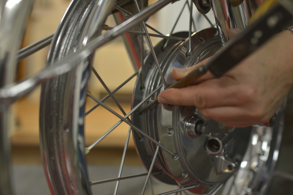
There a some motion blur on the hammer head, but you should be able to get an idea of its size, a small hammer will do nicely. The effect of doing this is, that the blow will move the head of the spoke a tiny little bit inwards, again making the spoke a little looser. When you have punched all spokes, make another last pass and tighten every spoke. This trick will maintain the tension on the spoke for longer, making you do without an additional tightening after say 500 miles (hopefully).
VERY important: When finished tightening all spokes, any surplus thread which protrudes out of the nipple, must be cut /grinded away, or you will inevitably have a puncture.
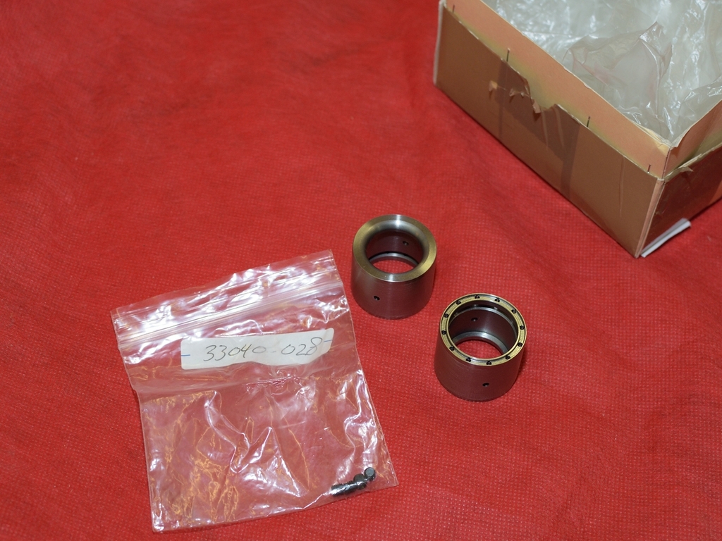
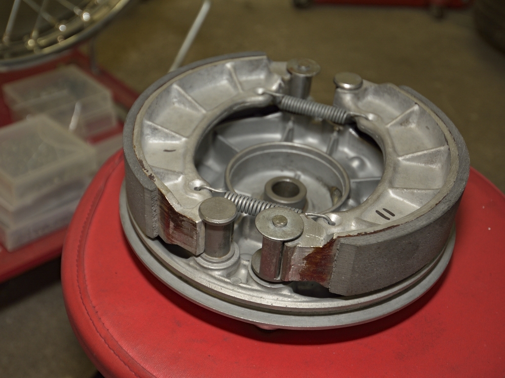
Remember this box on earlier in this thread:
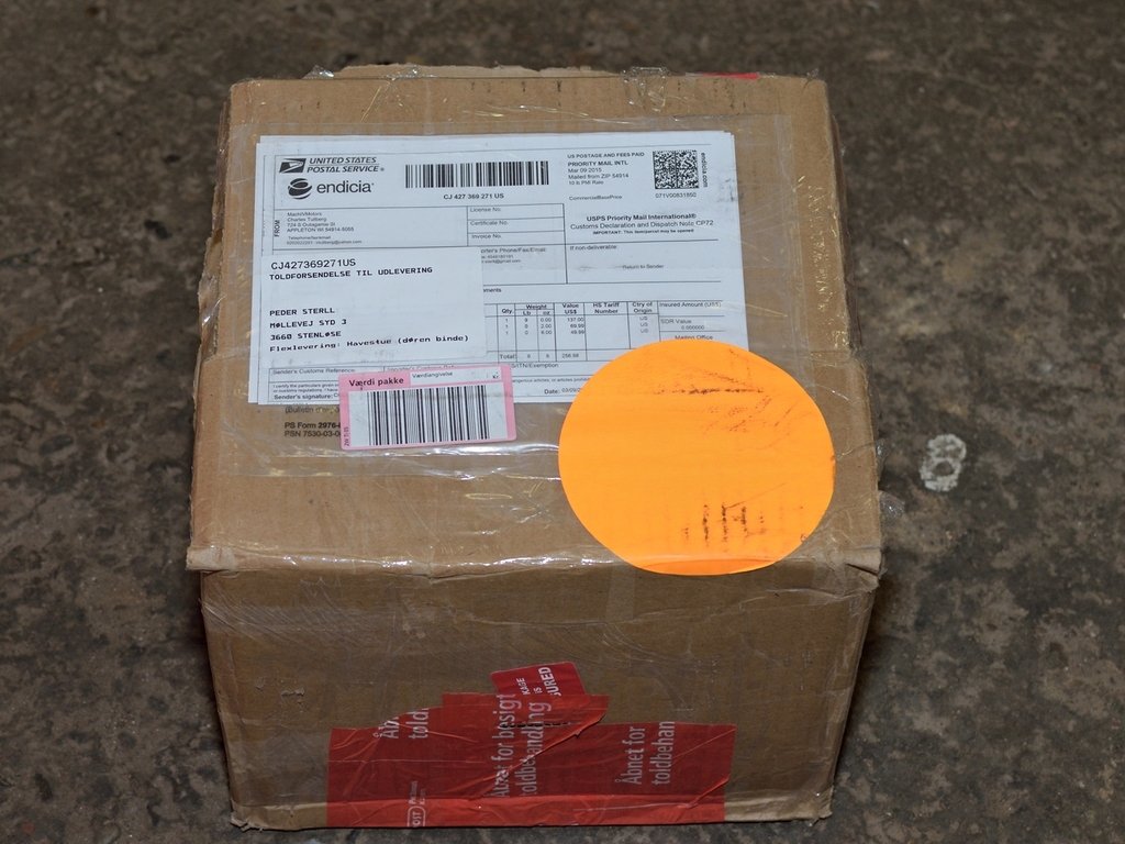
I forgot to mention what was inside:
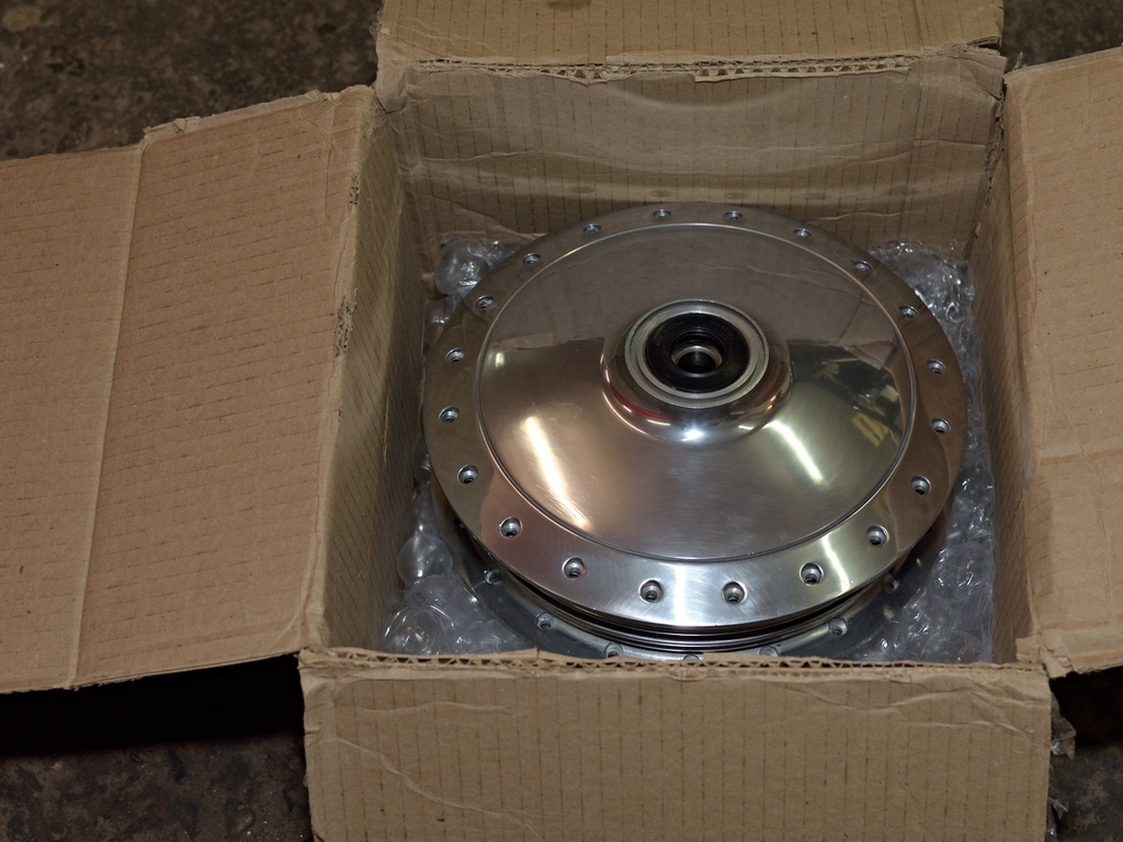
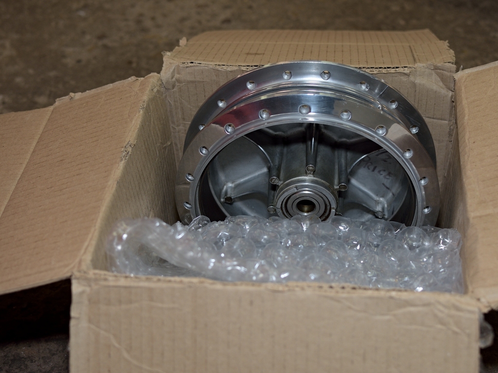
... a brand New Old Stock front brake drum for a 1969-70.
TA-DA
Bought on Ebay from MachIVMotors, and due to this, it wasn't even expensive:
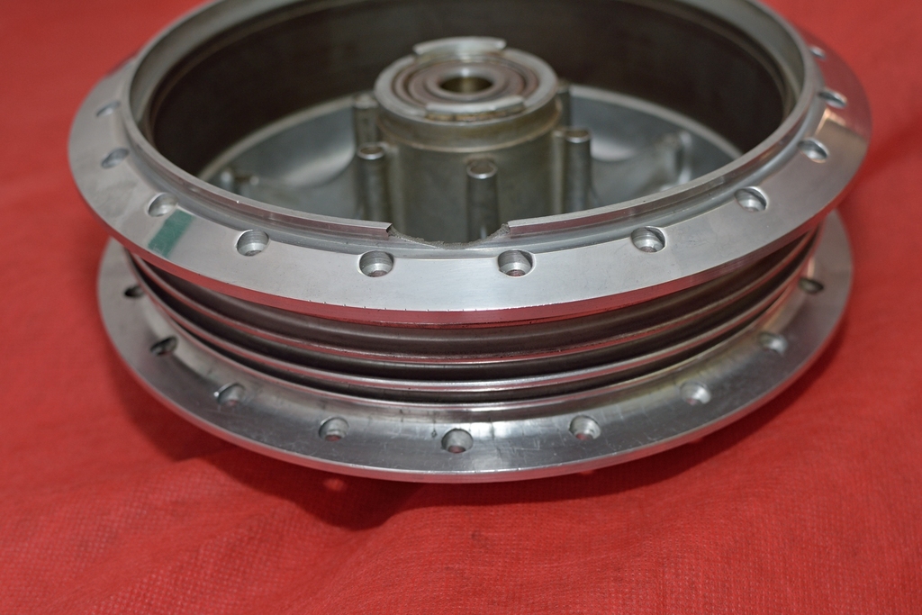
My old front drum was close to service limit, and I wasn't very keen on having
someone to machine out the worn steel band and crimp in new one.
From what I could read, some 60' -70' GM cars, as well as older Porsches
(Speedsters, I think) have the same alloy drums with steel band inside, and I
got the impression that they can be quite tricky to fix.
Of course the drums were made that way originally, but when say a machine shop
makes the fix, they have to be damn sure of the tolerances, as the steel band
will either become a loose fit, or be to tight (causing the alloy to crack).So I disregarded this "solution" and was very happy that I was able to get this
drum.
What do you guys with -69-70 models do ??
Not too far from me, there was this small machine shop, which specializes in welding alloy, and they had experiences from similar previous task. They price I paid could barely pay the coffee and donuts for the 5-7 guys working in the shop.
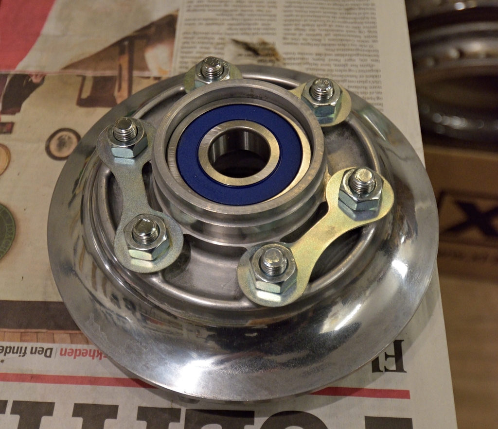
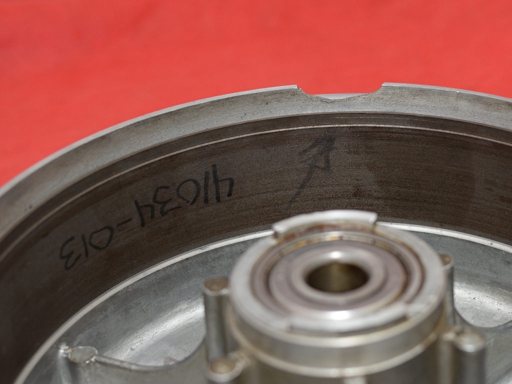
While the shirt was already buttoned up, I chose the put in new bearings and seals too. After some spit and polish, it looked like this:
Forgot to mention, that it got some new linings too. Linings are somewhat softer than the hardest one,. In this way I hope to minimize the wear on the steel band:
"The devil is in the details", I think it's about right. There sure are lots of bit needing attention, if you wanna end up with a result that you can be proud of.
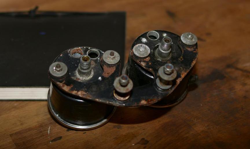
It's amazing that a horn can consist of that many parts. More
than 20 bits if you include 5 screws and 2 paper thin gaskets. A far cry from
modern electronics, as everything can be taken apart and reassembled.
It was the original Nikko, of the type only used for first 2-3 years, and I
think it's cute, so I decided to give it a make over:
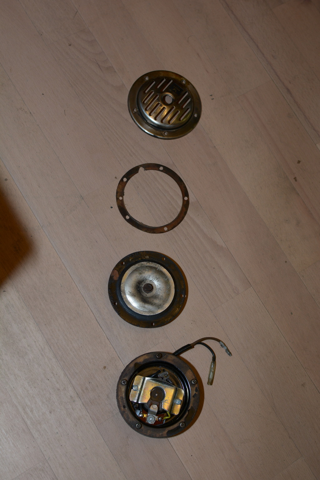
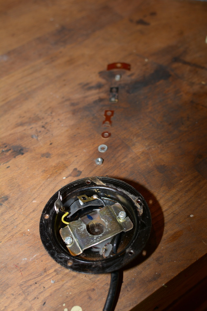
Everything worked fine, so just a quick cleaning and inspection.
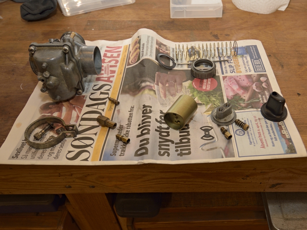
Next small item is the fuel petcock:
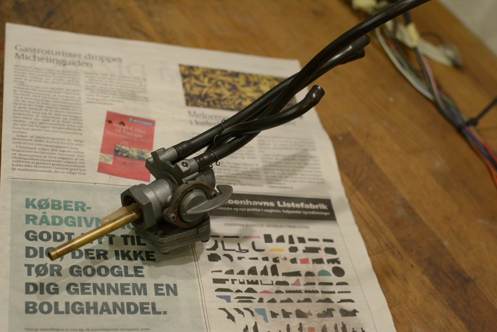
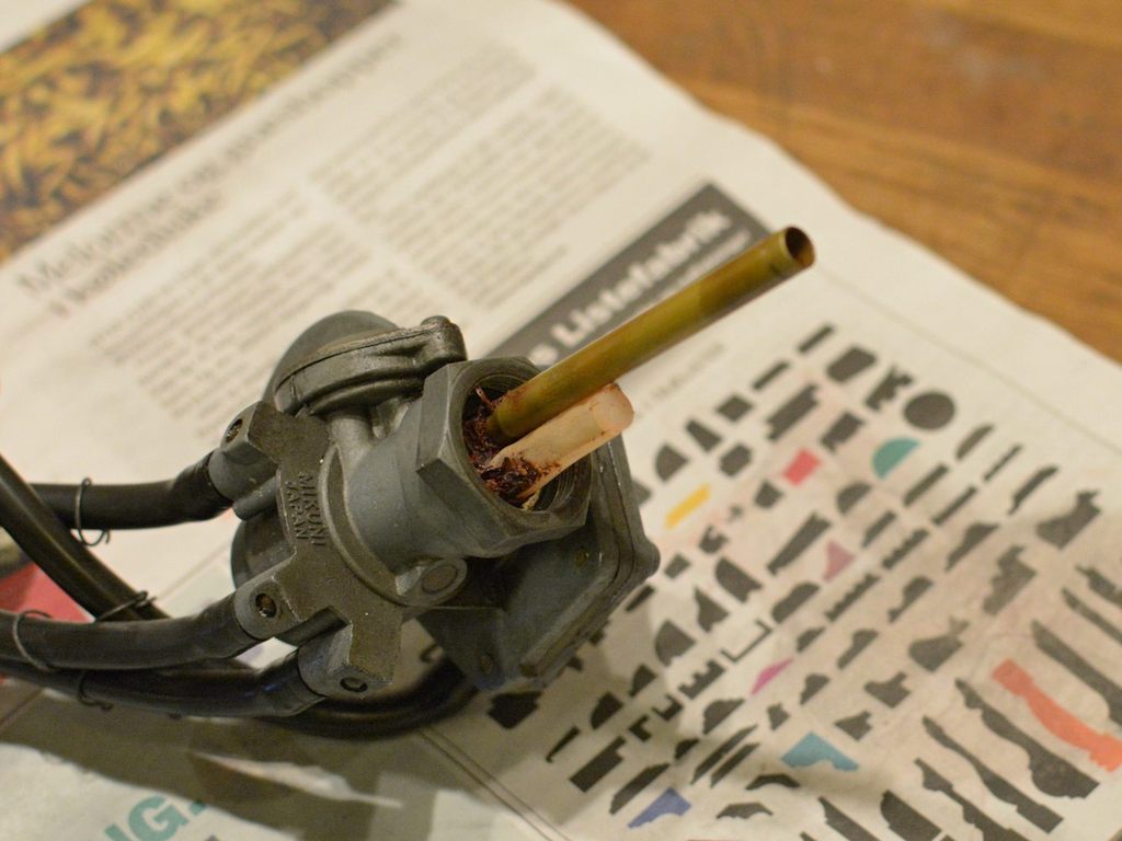
Bike had been standing for 7 years in my garage, and probably some years before that. Just as expected, it looked awful, full of red, rust coloured gum.
It was a pig to clean, even with the use of my ultrasonic cleaner, but I managed. New gaskets, springs diaphragm, screws etc.:

Not sure of the quality of those repro parts though.
Functions of the petcock is crucial if you wanna avoid flooding the carbs.
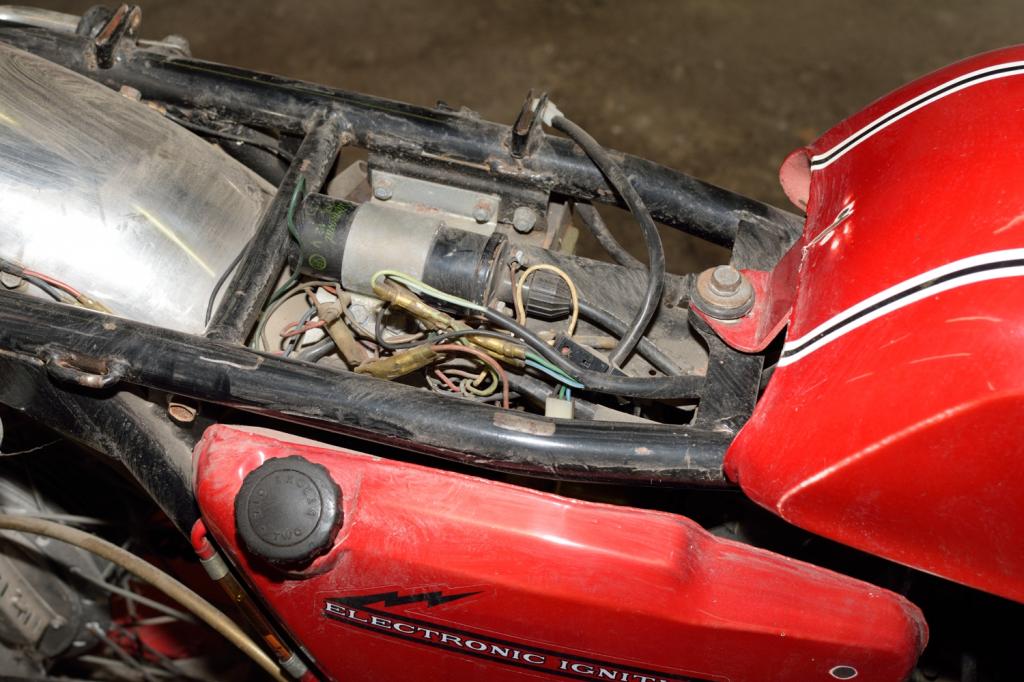
I was very much in doubt here. Wiring on old bikes has almost always been tampered with, and if repairs have been made, they are rarely made the right way = soldering the connectors to the wires. And so on ... There are complete main harnesses to be had on Ebay, Diablo Cycles and similar. Prices vary, but I never came to decide which one to buy, and most likely these would not have the additional wiring for city light, and for the 3 separate ignition coils. Mine is a Euro model, meaning that it has both these 2 features. With a brand new harness, I would be home safe, and could stay clear of electrical trouble, but for me restoring is also about preserving as much of the bikes soul as possible. Sounds damn romantic here, but it's true.
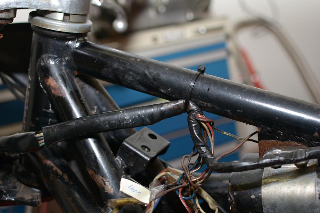
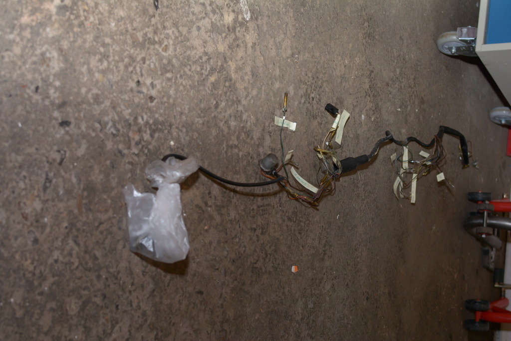
After a close examination and comparison with the wiring diagram for a Euro model, I concluded that apart from a lot of dirt and grease, a few broken wires, and some additional strange wiring including an extra fuse holder:
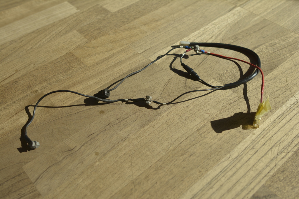
... my harness was in good shape, and very original. It even still had the small
numbering labels on it.
Long story short, i marked it up, removed the protection tube (which was torn
anyway):
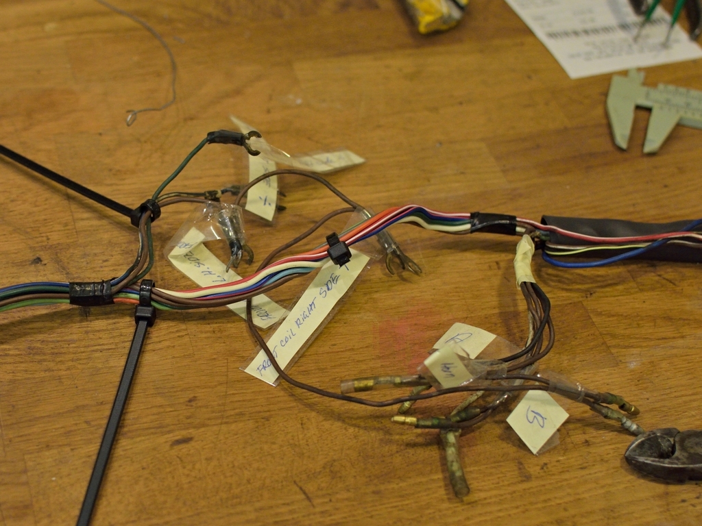
Cleaned each individual wire, checked the connectors and taught myself how to solder new ones to replace missing ones.
BEFORE & AFTER:


and last one:
Wiring for the Speedo- and Tacho lights were missing however, so I had to source
these on Ebay.
Its getting pretty crowded in the Head lamp body:

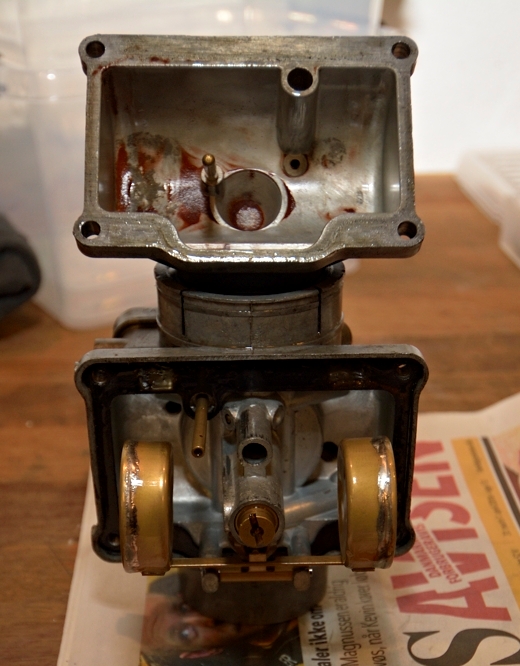
Now its time to start taking the carbs apart:
Hmm, just as expected the bowls were filled with lotsa reddish stuff, and it looked like it was way back since they had been cleaned... if they ever had:
Before cleaning can start, be sure to get rid of all traces of gaskets, and
remove the all pilot jets, air screws, idling screws (take care not to loosen
the springs and washers) and last but not least, remove the main jet tube, by
unscrewing the main jet and removing the special washer btw. Main jet and Needle
jet. The Needle jet can be tricky to remove, but tap on it lightly using a
mandrel of as large a size as possible.
Don't get too alarmed by the look of the Needle jet, after it has been removed,
you will probably want to replace it anyway together with the Needle. (More on this topic later)
It might be a good idea, to write down each individual carbs settings while going along...
Before just sinking each carb into my ultrasonic cleaner, they are allowed a nice long bath in diesel oil:
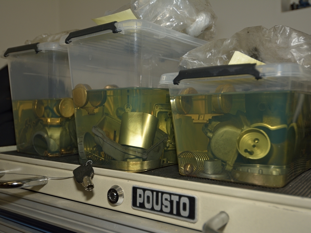
... each carb have now been completely dismantled, and care is taken not to mix up the individual parts.
After a couple of weeks much of the dirt an "gum" have loosened. After a brief cleaning, I can pour them into my ultrasonic cleaner - one at a time. But first some words of caution: Carburetors are made of some light alloy, and all the small drillings, holes and vents are delicate stuff.
This is why I:
- note / write down / take picture of all the small brass plugs in each carb.
They are know to work loose during cleaning, so be careful when you remove the carbs after
cleaning, and use a filter when draining used water from the cleaner.
- pour them into diesel oil first, to avoid having them in the ultrasonic
cleaner for too long.
- don't use anything like strong detergents. I've heard of someone using
dishwasher soap. This is very aggressive to light alloy, so I advise that you don't.
- use hot water with only some soap
added, or you can add a small amount of the the type of cleaner, that painters
use to clean the wooden parts before sanding/painting.
I applied about 85% power (max power = 240 W) for 20 mins in my cleaner. It can easily hold two carbs at a time (capacity 10 Litres), but again, avoid to mix up the parts, so I did 3 runs.
... but of course, I managed to lose one of the plugs during ultrasonic cleaning. This one:
(picture taken before cleaning)
So I spent some days looking for shops where to buy some brass rods in approximately the right diameter. Incredible what you can buy on the net today. A piece of correct length was cut out, ends grinded smooth, and it was almost a press fit, but I added some 2-component "Alraldit" glue as well. Epoxy based stuff but better safe than sorry.
Checking the float level:

- one float had a dent, but to be sure, I replaced all three.
I wanted to use as few Keyster or Sudco parts as possible, and as many original Mikuni, but this is no easy task, as many of the original Mikuni parts (easily recognizable by the small logo) are no longer available.Main jets, needle jets etc. can be found as original parts, but the tricky bits are the jet needle and the needle jet. To my luck there is this great company in Sweden, my neighbour country: http://www.braigasen.se/ The company name can possibly be translated to "good throttle response" or similar. The owner was very patient, as it took quite a number of E-mails before I understood exactly what was possible / not possible.
A 1970 Euro H1 should originally have a 5EH7 Jet needles in a 194 #O-2 Needle jet, if its to be in standard configuration. The 5EH7 needles was obtainable on
Fleabay, but the 194 is not in Mikuni's stock any more, so Christer eventually
modified a 159-O2 needles like this:
1. Shortened the overall length of the Needle jet by 2mm
2. Lowered the shield to 2.4mm
3. Drilled and made new thread in the needle in order to accept Jet N100.604
Its important that both the Jet needle and the Needle jets are corresponding, and that both are renewed during a resto, as these parts will wear over time, due to the needle sliding up and down (most UP, I'd guess) inside the the Needle jet. Additionally, Christer also supplied the necessary gaskets, float valves etc. Nice work!
Almost finished (apart from float chamber screws):
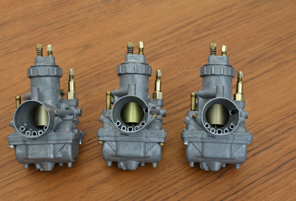
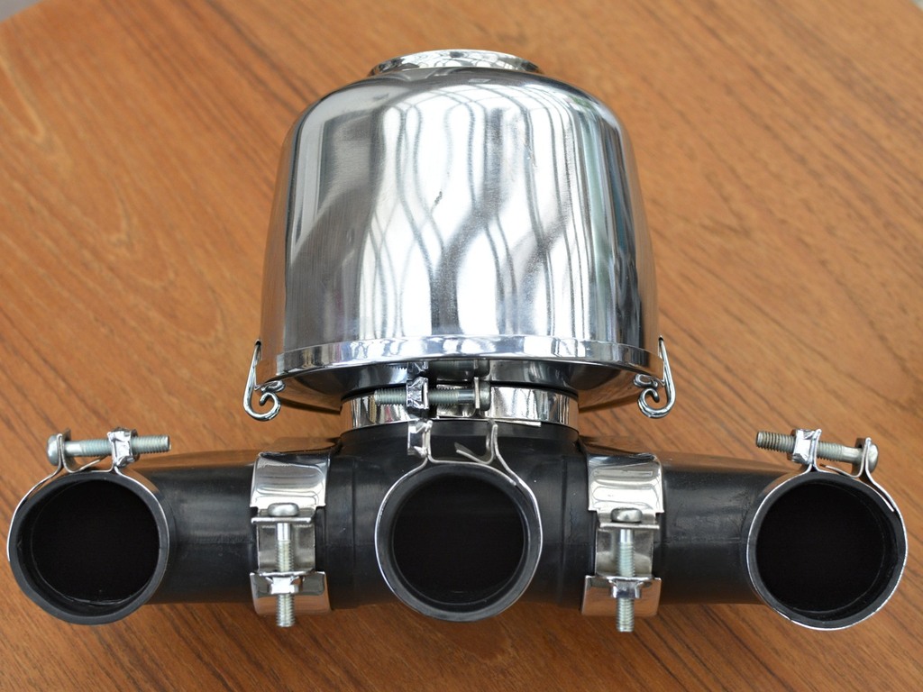
Finished:
However, I will need 1 new (or 3 new) clamps for the rubber tubes, as one in the
middle is close to breaking.
Have ordered replacement parts from Diablo, but I
would have preferred the original ones, of course. But let's see how it looks
when they arrive...
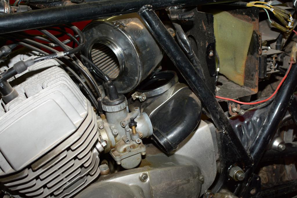
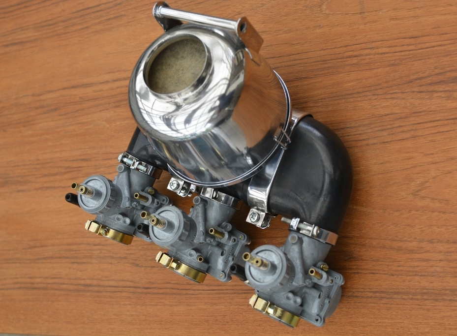
The Air box canister looks too shiny ??? But it was like that when I bought the
bike back in 2003.
This little gem came to me, in cold Scandinavia, all the way from Southern Italy
- and it worked:
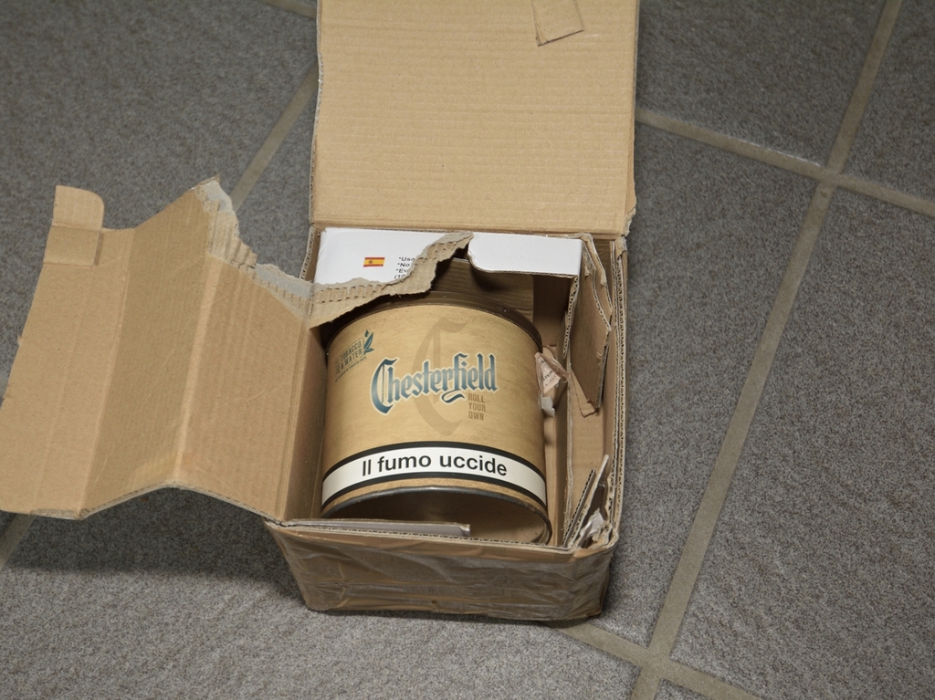
... probably in need of a complete strip-down / rebuild, and the chrome ring is
wrong, but at least it's for a H1, unlike the one which came with bike.
Wrapping was excellent, by the way: An used tobacco can equipped with a warning
sticker stating that smoking kills you, in Italian writing. Very fitting for
Kawa triple parts, I think!
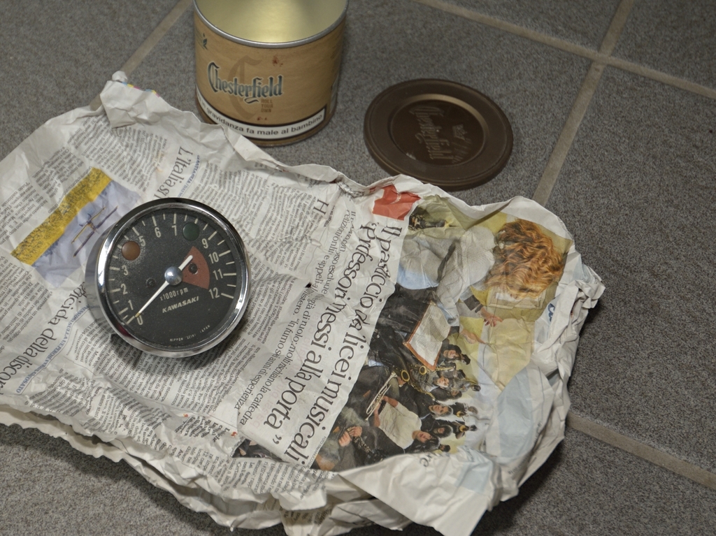
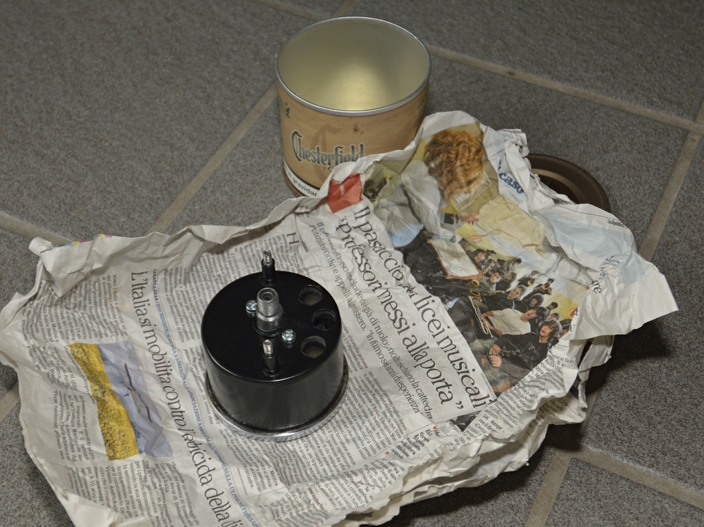
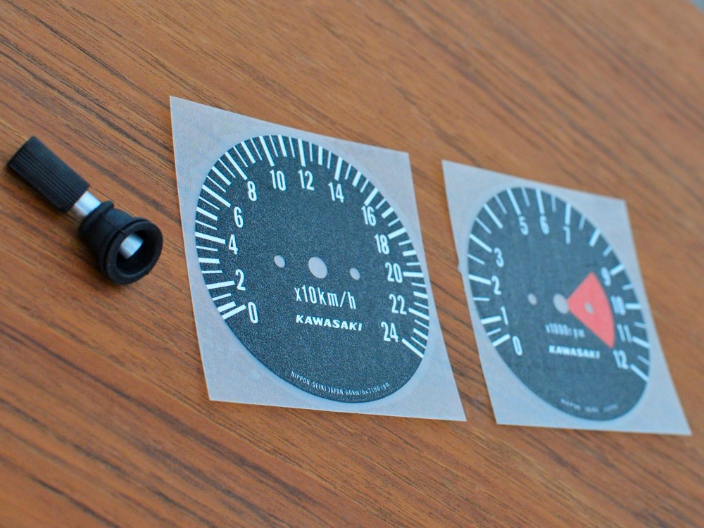
... Now I have one speedo which works, but in need of rebuild, and missing the
reset knob + two rev counters and some repro dials.
It's time
to send everything to Northern Sweden, where one of the very last companies,
making instrument refurbishing lives...
Btw. I managed to find the reset knob on Fleabay, too:
I'll get back to the Speedo and Rev counter when they are back from the shop. Might take a while.
I was not happy with the exterior finish of tacho and revcounter, when they came back from the specialist shop, so I had them re-finished:
Still NOT perfect, but I'll guess I'll have to live with it ... which I will.
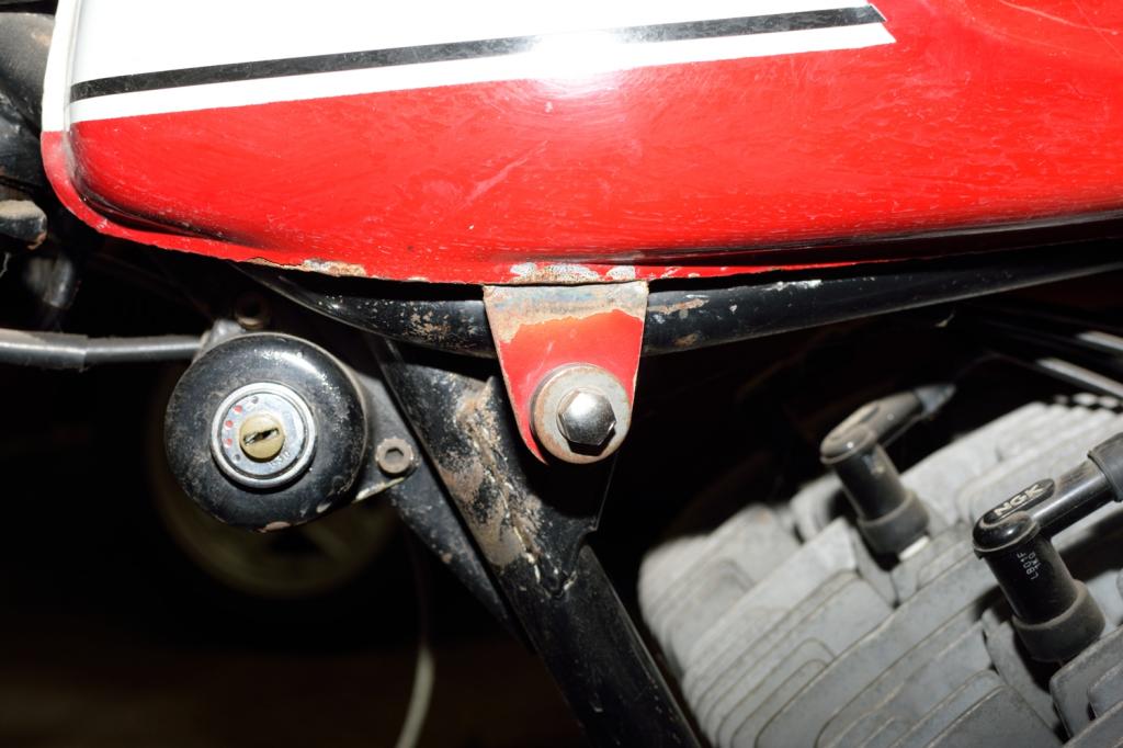
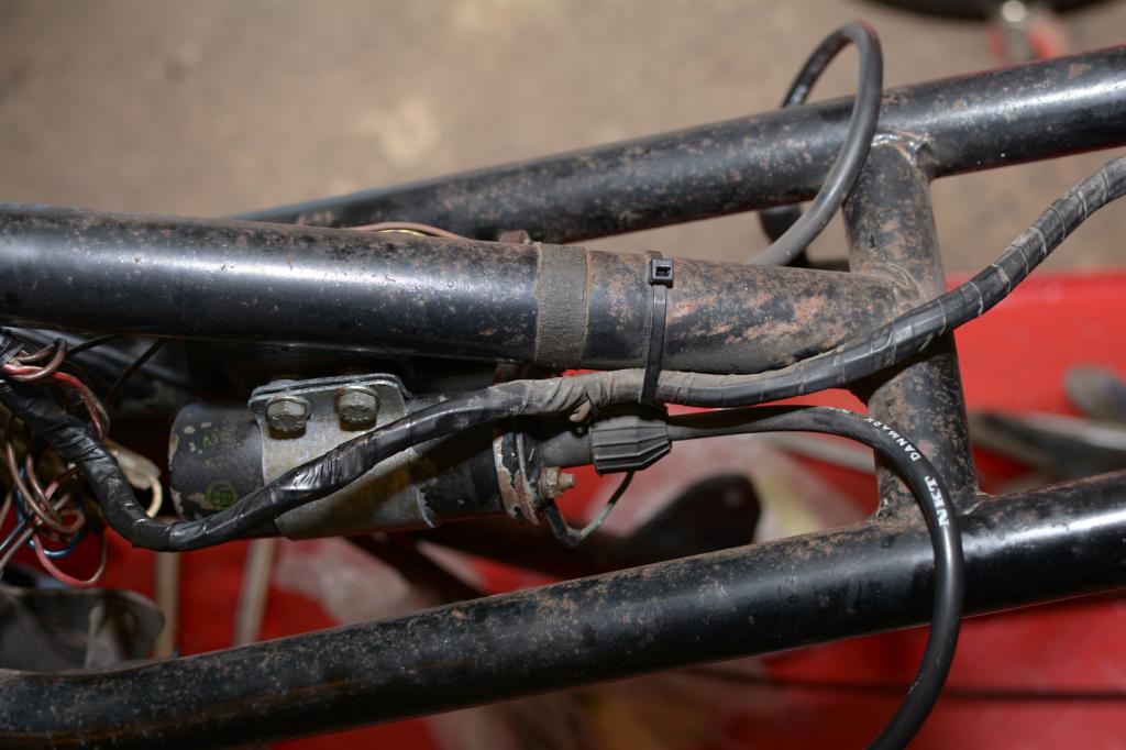
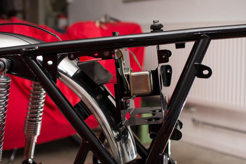
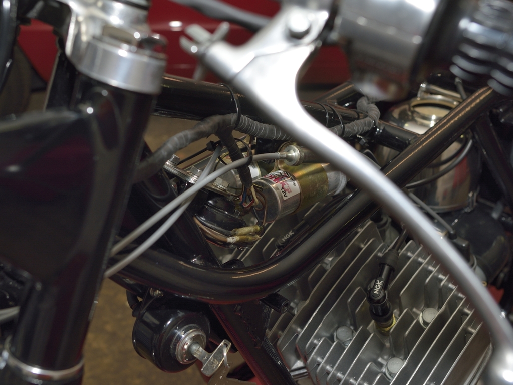
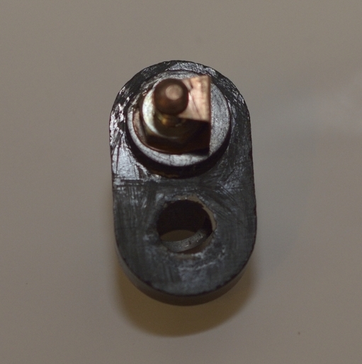
QUESTION: Does this part belong to a H1?:
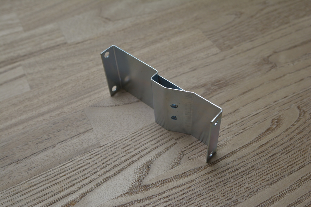
Yep - it's the bracket which supports the coil for the mid cylinder.
The 2 holes are for attaching the clamp for the coil. Due to the weight of the
coil and the vibrations, the bracket had cracked all way through the holes, from
edge to edge.
A new one is virtually unobtainable, so I had the bracing done. It
will not be seen as it's located at side facing downwards.
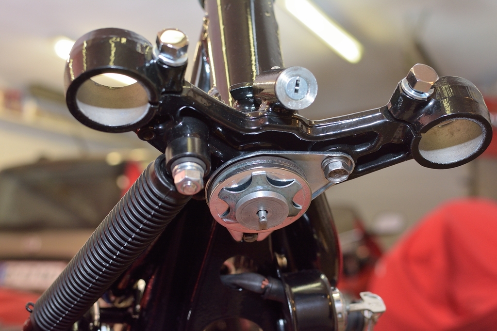
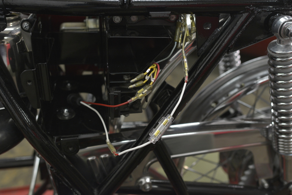
Next pics shows coil + bracket and their location in frame:
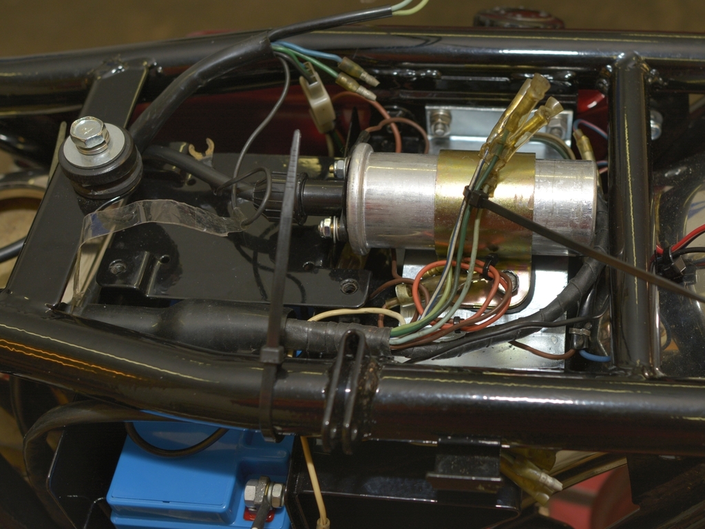
- now I will be able to finish off the wiring loom and make some tests!
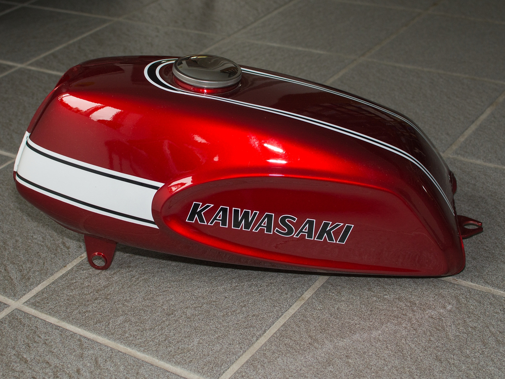
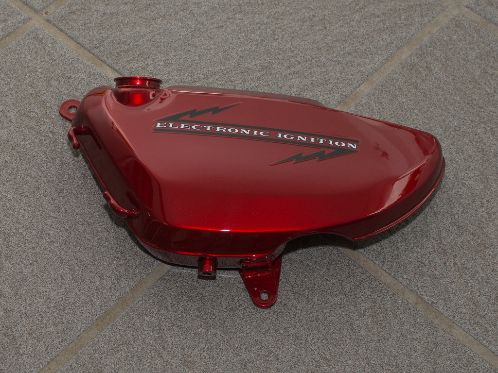
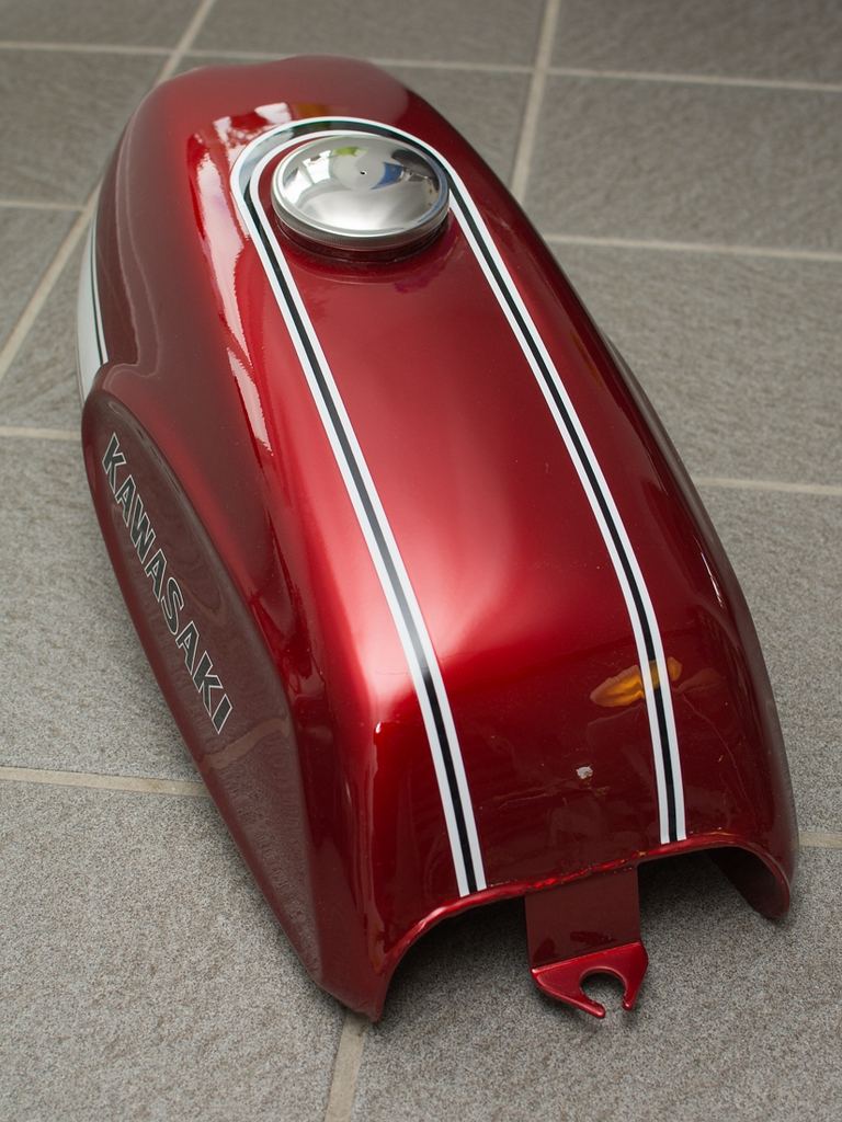
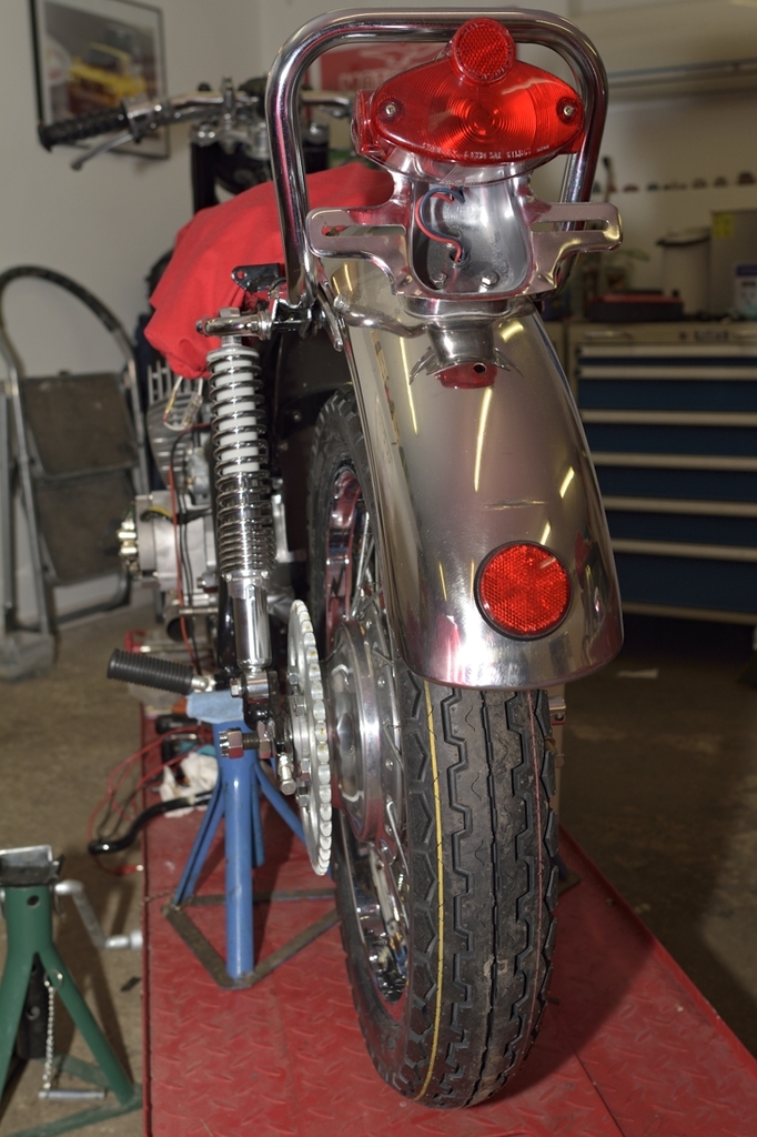
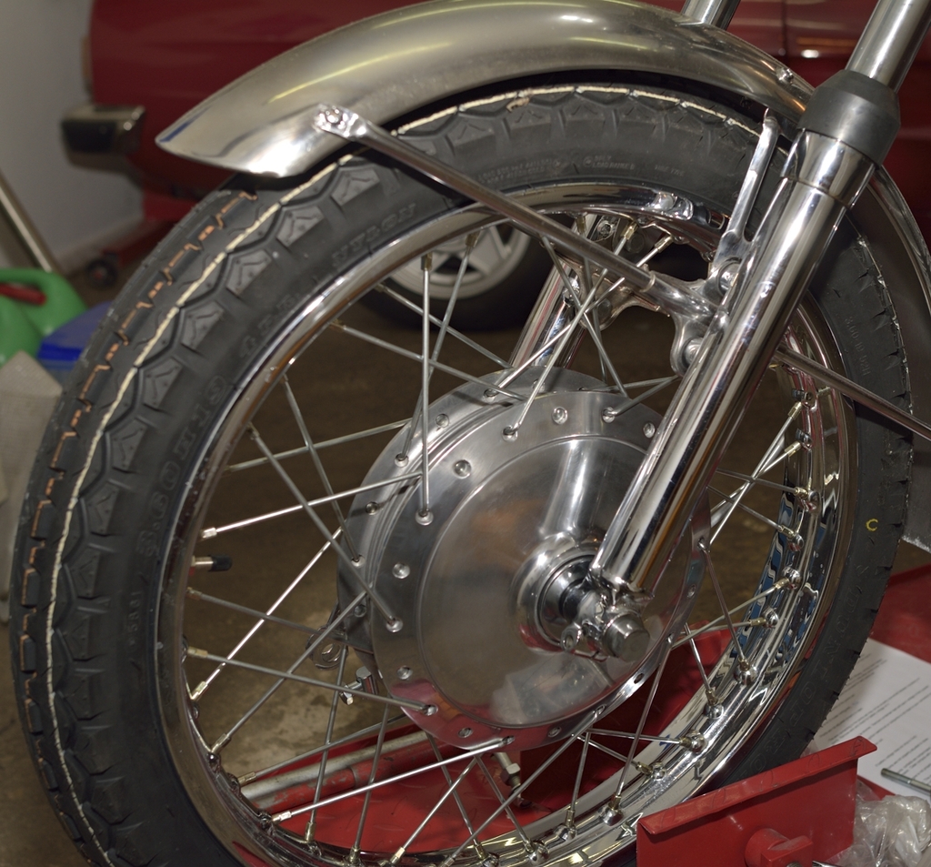
And now to something more colourful! The paint shop has finished the work:
Yes, front brake is done now:
... using an original Takasago rim.
When I told the story of how I obtained a NOS brake drum, at the brake shop, he
advised me to have a relatively soft lining fitted to the shoes. Let's see...
I'm not going to race this one.
Yep, the painter is very very good. He did a Honda CB 750 K2 for me, years ago.
Same quality. A very calm, humble guy, with a small shop. And not even a Web-site has he got.
Life goes on.
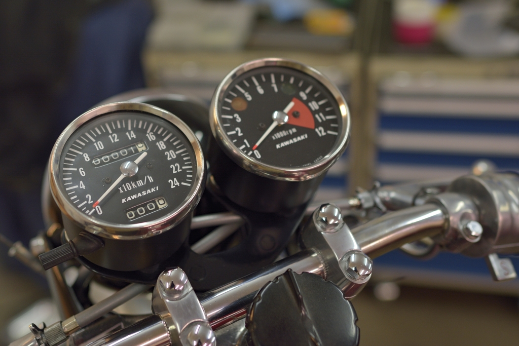
Tacho and speedo now back from the specialist company who did the refurbish. Nice result, but I 'll have to apply the last finishing touches to the external parts. Will come at a lager stage...
Dials should be just right for a KPH version, I think:
Don't mind the black plastic strip in the middle. I'm experimenting a bit with
routing of cables...
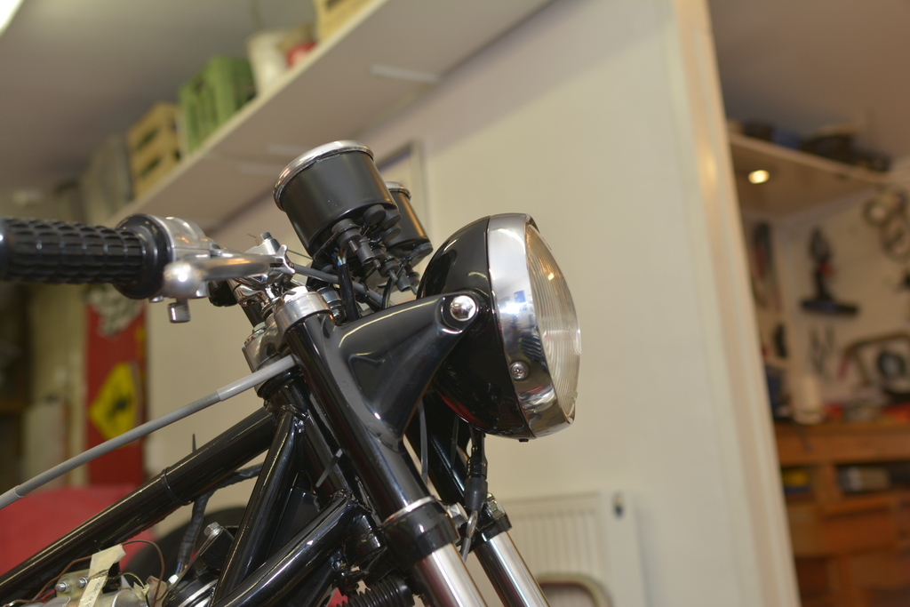
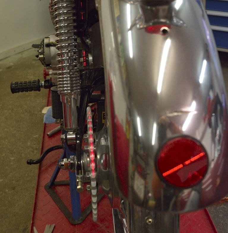
Nice to turn on the light and seeing the idiot lights all go on - except the one
for the generator, as the engine is not in place. Won't be for long now ...
Also managed to squeeze in all the wires in the head lamp .Original Stanley Sealed-Beam btw.:
Next update during up-coming weekend. Will cover engine, and what has been done here. Stay tuned!
The day before Christmas eve, I finally had time (took a day off) to cross "Øresundsbroen" - which connects Denmark to Sweden:
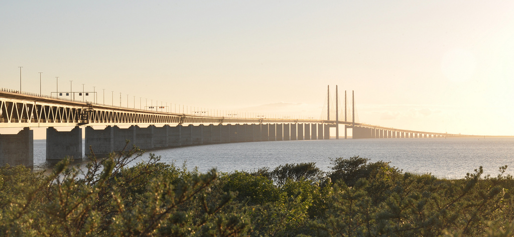
It's a combined tunnel and bridge, with an overall length of approx. 9,9 miles. It was early morning when I crossed. The sun was slowly rising from the heavy rain clouds in the horizon.
I was going to pick up my Kawa engine/gearbox which for the last couple of
months have been at the Swedish two-stroke wizard Ebbe Parnestål.
Eptune, Ebbe's shop, is located in the outskirts of Malmø. He deals almost
exclusively with two-strokes.
Looking forward to see the engine again and to some holidays, my spirit was
sky-high when I crossed the bridge.
You can see some of Ebbe's previous work here: http://www.ebos.se/eptune-triples.php Pretty amazing stuff I think!
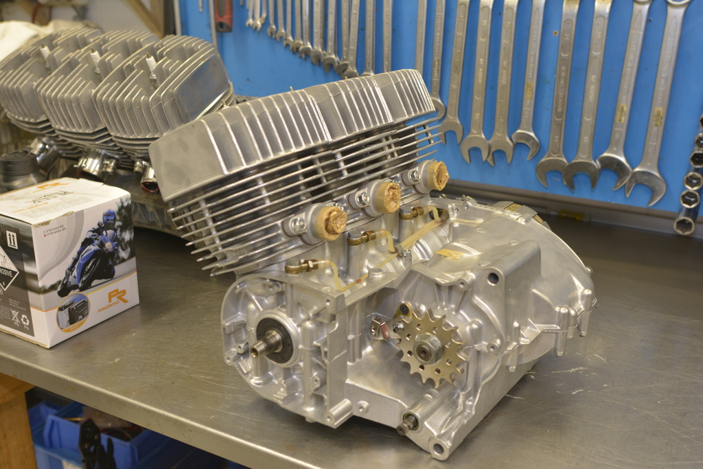
This is how it looked when I picked it up:
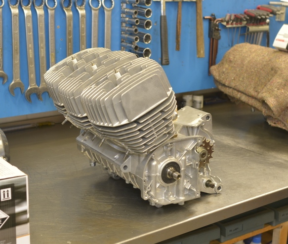
Soo nice - I think it deserves a couple more pics:
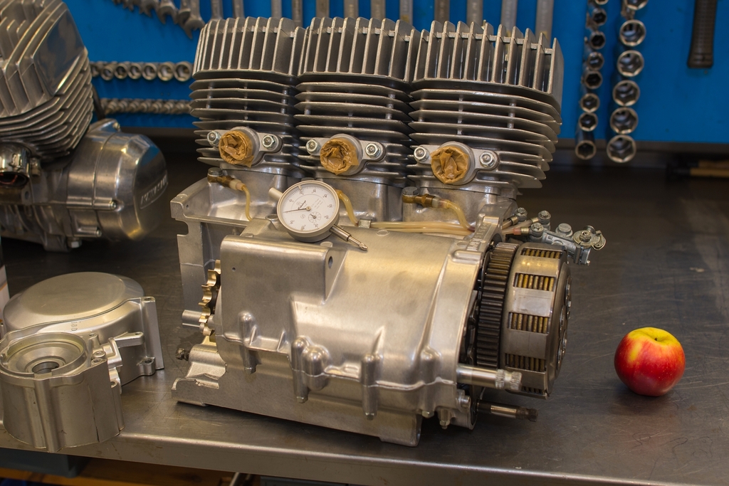
There is always a number of triple engines on Ebbe's desk, and very recently he refurbished a H1R engine from a barn find. Bike now with a Swedish collector undergoing restoration.
Actually I would have enjoyed assembling the parts myself, but after all, Ebbe can do that much faster and better than I would have been able to, considering his huge experience.
Note: Not sure if "ball polishing" makes any sense. I have in fact made a 1-to-1 translation of the Swedish term. When reading about the process from the Swedish company, it's kinda like a big tub clad with rubber on the inside. In the tub are 1.2 tons of small stainless steel balls, 1-5 mm in diameter plus some anti-friction gel. The parts to be polished are sunk into this tub, and it vibrates with a frequency which also makes the parts rotate in the tub.Any which way, the result is excellent, very gentle to the surfaces, and the resultant look, is neither too shiny or too dull. From what I have read on various MC sites, the finish is very long lasting. Only drawback is that you must clean the parts meticulously afterwards. But I guess this goes for vapour blasting as well.
Just one more picture, to emphasize the difference btw. before and after:
... and it wasn't even bad before. Let's continue the story.
A grown man can easily carry the weight of the engine, but when it's to be placed in frame, you need to be two:
... nice to have another grown man to help you.
The frame tubes were of course covered with rags and similar, while engine was
lifted in place.
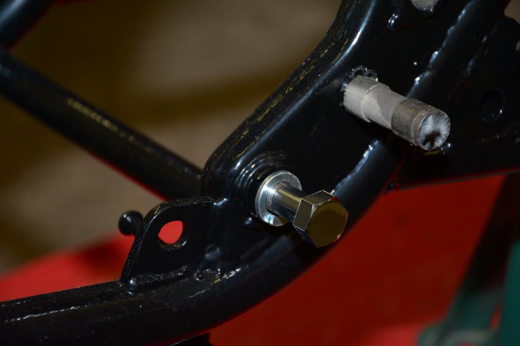
So now it sits there, but nothing more. Awaiting the right (small) 10mm nuts to arrive.
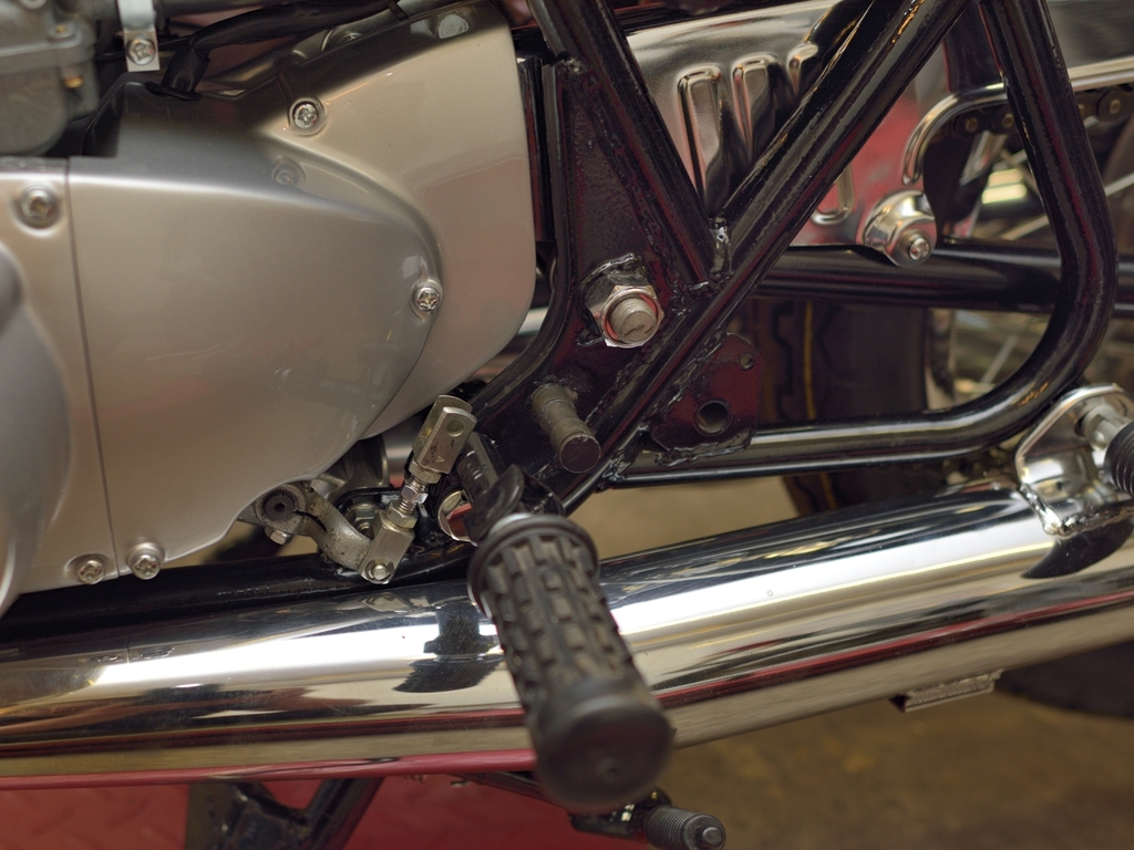
As mentioned earlier, I will use a small, flat bar (euro
style), combined with new repro style gray cables, this is a bit of a challenge.
The speedo and tacho cables are of course vanilla, as these are independent of
rise and width of bars, and this goes for the front brake cable as well (almost).
But the throttle and starter cables, did require some creative thinking. And so does the clutch cable! First try:
... won't work! After 3-4 attempts, this seemed to work well:
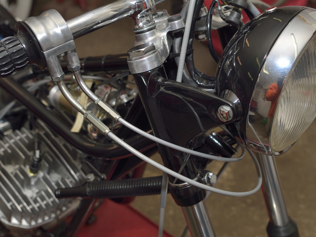
Not quite the original cable paths, but to honest I don't give a damn, and I'm not prepared to pay like 150-200 USD + Danish customs + 25% tax + a handling fee.
Now to the neutral indicator. Wiring is ready:
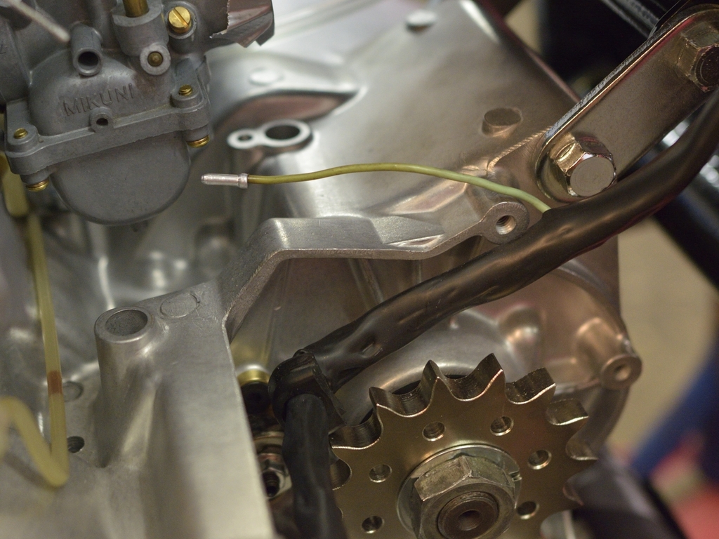
And so is the indicator itself. The black bakelite was broken, so I sourced a "new" on Ebay. After dismantling and a thorough cleaning, it looks like this:
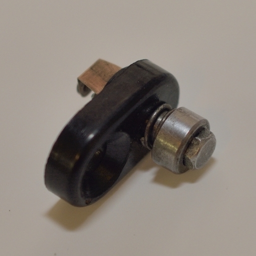
Notice the way the small brass lever is pointing. This is vital, if it's to
function properly (thanks to Per Olofsson from Swedish Classic Kawasaki Forum).
I apply a very small amount of sealing compound to the black bakelite before
tightening it to the gearbox using the correct screw.
Lots of details needs attention now, and I'm compiling it all together trying to get an overview of what's missing.
Besides from that, I got the right 10mm nuts for the for bolts fixing engine to frame. And at the same time, I found some nice OEM shims in UK:

So engine is now shimmed, securely tightened to frame, and sprockets were laser aligned in the same job.
Being new to triples, I've been reading a lot about petcocks (and hydrolocks).
Mounted the petcock on the tank but realized that I might take it apart again,
to ensure that the lever is not pitted.
Also bought some special tape for sealing the treads, but I need to check for any leakages tank can be considered finished. More to follow ...
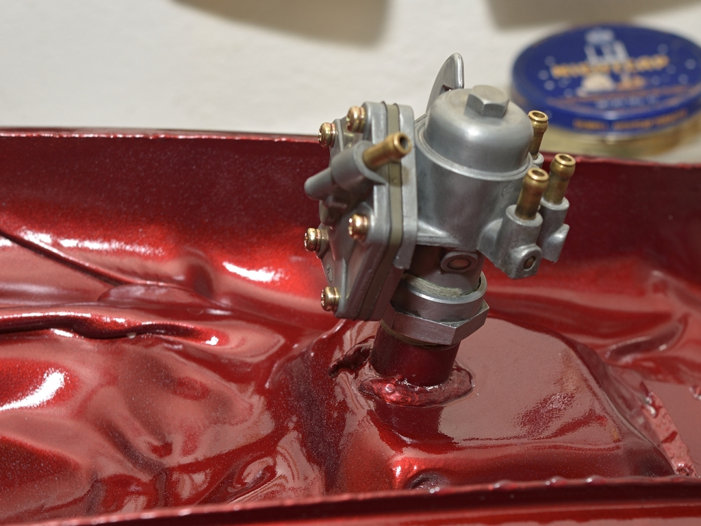
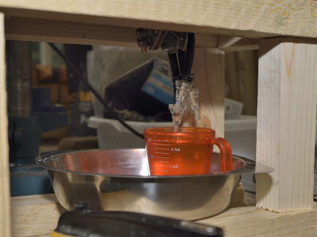
Ok - I built this ingenious device so I could test if tank and petcock leaked:
Of course it leaked, but not where I expected it to. It leaked around the lever,
like if some gasket was missing.
But AFAIK there should be any gasket - right ? Anyway - after emptying the
tank, the petcock went off again.Will have to work it over again, more on this later...
Made a second try with the petcock. Still leaking, but not as much as before -
what a consolation!
Spirits are low now - time to administer the euthanasia: Reading the Maintenance
Guide! After a short while, I realized that the fault was all mine:
I had placed the
big round spring washer between the petcock body and lever instead of btw. lever
and the plate which holds the lever in place. The one with text "ON", "RES" and
"PRIME".
Will make a new test tomorrow when there's light outside (winter time here in
DK, it gets completely dark outside at 17:15 hours).
And I won't be inside my
shop with gasoline pouring out everywhere.
Ok - as mentioned earlier, I managed to assemble the petcock correct in only 3 attempts. It's now completely tight, so today I did a test, where I set the lever to "PRI" at let it fill a container with 250 ccm, and measured the elapse time. I did 3 attempts, and the average time was approx. 20 sec. As I wanted to come as possible to real life circumstances, I left the fuel cap on the tank, securely tightened, and I mounted some fuel lines with the type of external filter I intend to use. For information, there are also 2 filters on the petcock - plus the strainer. Perhaps overkill ??
I made the assumption that
petcock performance is the same, regardless of lever is in "ON" or "PRI"
position. ( I had no way of creating vacuum).
The conclusion is
that it delivered slightly less than twice the amount needed when running WOT. I
came to this from interpreting this chart:
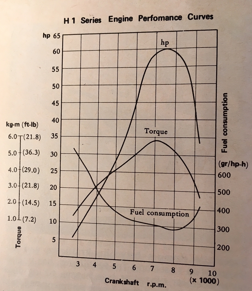
... where I pay specific attention to the fuel consumption graph which is
measured in grams pr. horsepower pr. hour,
7.500 rev/min (max Hp performance)
consumption can be seen to be approx. 300 grams/hp /hour or 18.000 grams/60
Hp/hour.
So with the knowledge that Gasoline (EN 228) weighs about 720-755 grams
(at 68 deg. Fahrenheit) the petcock performance can be translated to:
540
grams/minute (because 250 ccm = 1 Litre in 80 secs = 720 grams in 80 secs).
I was relieved to learn that petcock performance is sufficient. Luckily, I'm not doing this for a living, cuz' I would have starved to death!
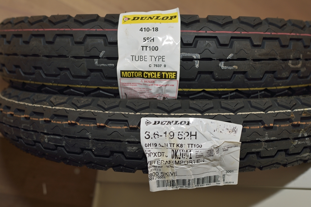
I managed to find them on this site http://www.wheelhousetyres.co.uk/130-80-18-66h-dunlop-tt100-gp-rear.html (I' m not related to this company in any way). Mine however, are the non-GP compound, which makes them considerably cheaper. But I guess I'll have to ride more sedately (which were my intention anyway). There are other bikes if I want to drag a knee:
Drove by the paint shop today. The engine- and clutch covers weren't finished, but he was actually working on it. When I took them off, they all had minor scratches, and the generator/points cover. LH side even had some dents. He's doing a great job, and I'm sure they will look brand new when he's finished.
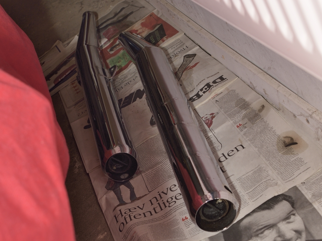
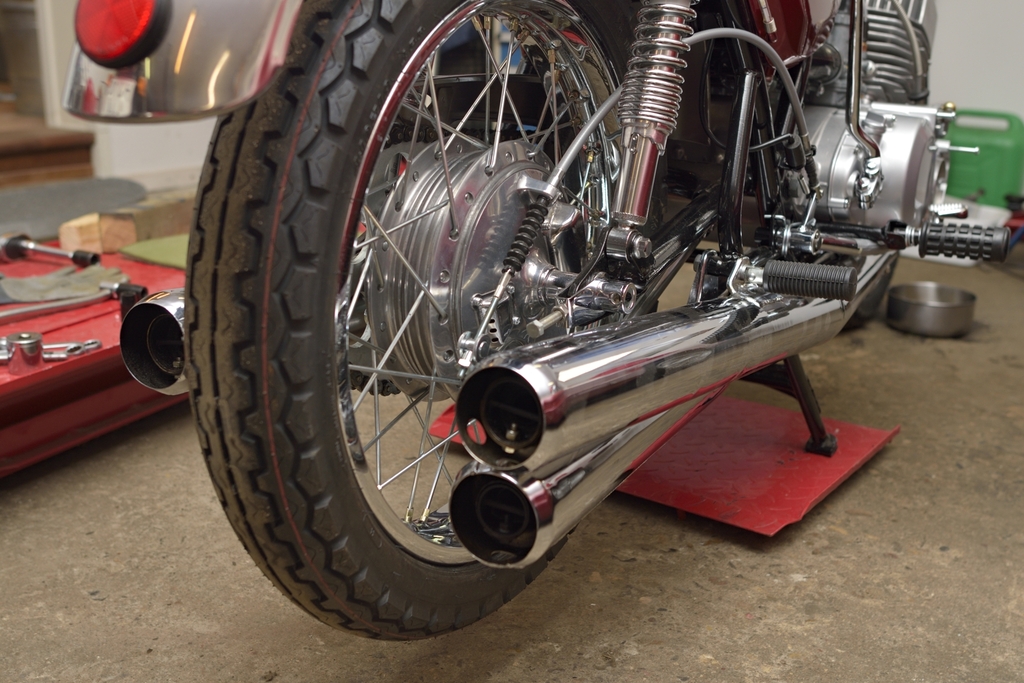
As I' m still waiting for some parts and a paint-shop, I decided to have a look at the exhausts. They are nice (one of the reasons I bought this particular bike) but not perfect, and I intend to keep them as they are, at least for now and the next couple of summers. So I started polishing the mufflers - again, not perfect condition, but definitely acceptable:

You can get a set of repro pipes from Doremi, but they are out-a-stock for now. Not sure about the quality, but at least they look nice on the web.
The Exhaust pipe holders (18069-024) were in very good shape. You can get them on Ebay, but these were made looking sharp again, after a bath in my Ultrasonic
cleaner.
The various muffler clamps are new, though.
Adding some new copper gaskets for the exhaust + some nuts and spring washers,
things came to look like this:
Time to give the ignition system some attention:
When I got the bike - back in 2007, it still had the original Diamond TU-29
coils. I've kept them of course, but I have bought 3 new ones, which are now
fitted. The main components, except from coils, HT cords and caps, can be seen here:

The wiring harness was in good condition, apart from the outer protection tube, which I of course renewed. Pretty awkward job!
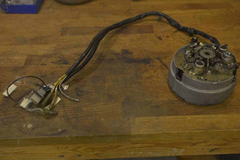
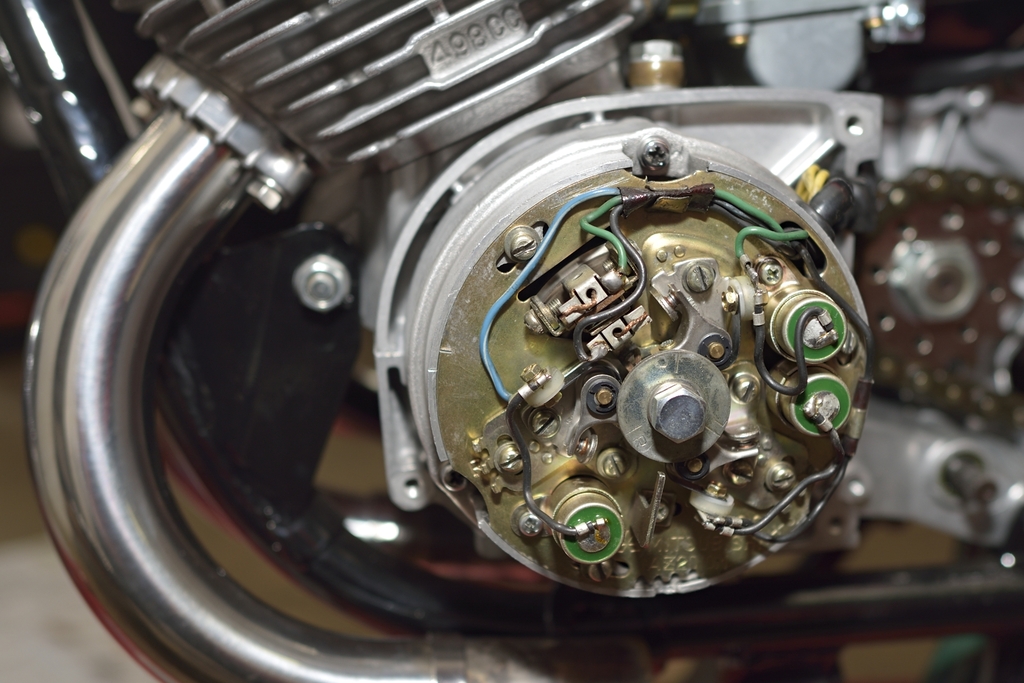
I Also renewed the contact breaker points and the condensers, which are in fact the same as on a H1B. Carbon brush and holder looked OK after a cleaning, and there was plenty of carbon left. Rotor was cleaned carefully, by hand and inspected. As it looked OK with no scars or broken wires (judging from a visual inspect only) it was re-fitted. The central cam actuating the 3 breaker points looked to be in very good condition for it's age. With a micrometer screw, I measured the differences in diameter around the cam to be approx. 0.05 mm, so it will be slightly polished by hand, and then reused. The whole assembly looks very "busy": Some screws still in need of replacement. But apart from this, I'm ready to start doing the ignition timing for the very first time.
I have always wanted to able to measure piston TDC exactly, and I also prefer to adjust the ignition setting according to piston position before TDC, rather than fumbling with a clumsy degree wheel.As I will be doing the ignition timing in a not too distant future, I bought this on Fleaybay. .. from Poland, I think. Cost me like 7 USD plus 6 dollars in shipment. It's very well made, solid and with a good finish. The thread is 14 mm, same as for the spark plugs, and it fits nicely. But I wanted to get rid of the ruler...... so I can mount one of my Dial-gauges...
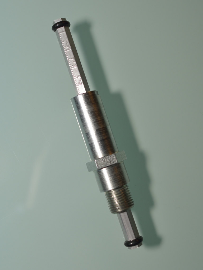
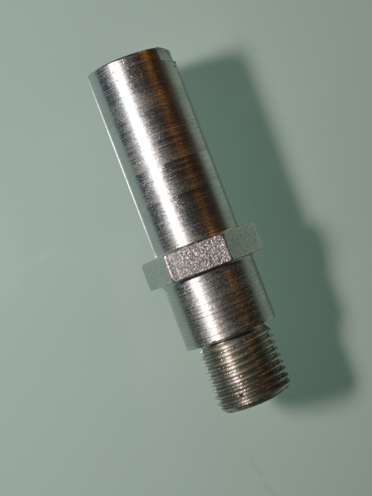
Next step was to drill a 4,2 mm hole, perpendicular to the large tube, and cut a 5mm thread. Then I milled away some of the metal in the top:
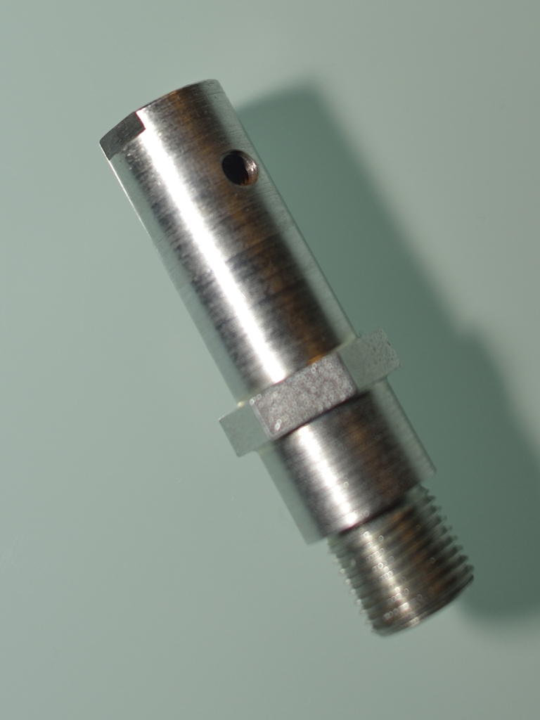
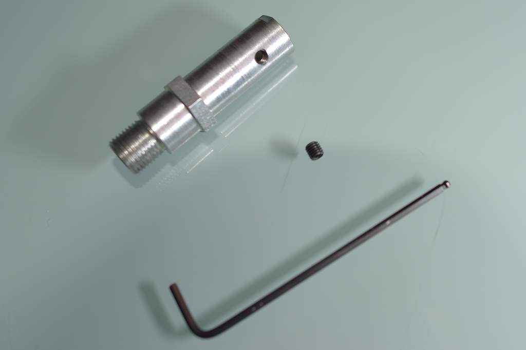
In the 5mm thread I fit a little Allen screw, just to prevent the dial gauge
from moving. I had an extra extension tube for the dial-gauge.
It needed to be
shortened a bit, and I rounded and polished the tip of it, so it won't scratch
the top of the pistons.
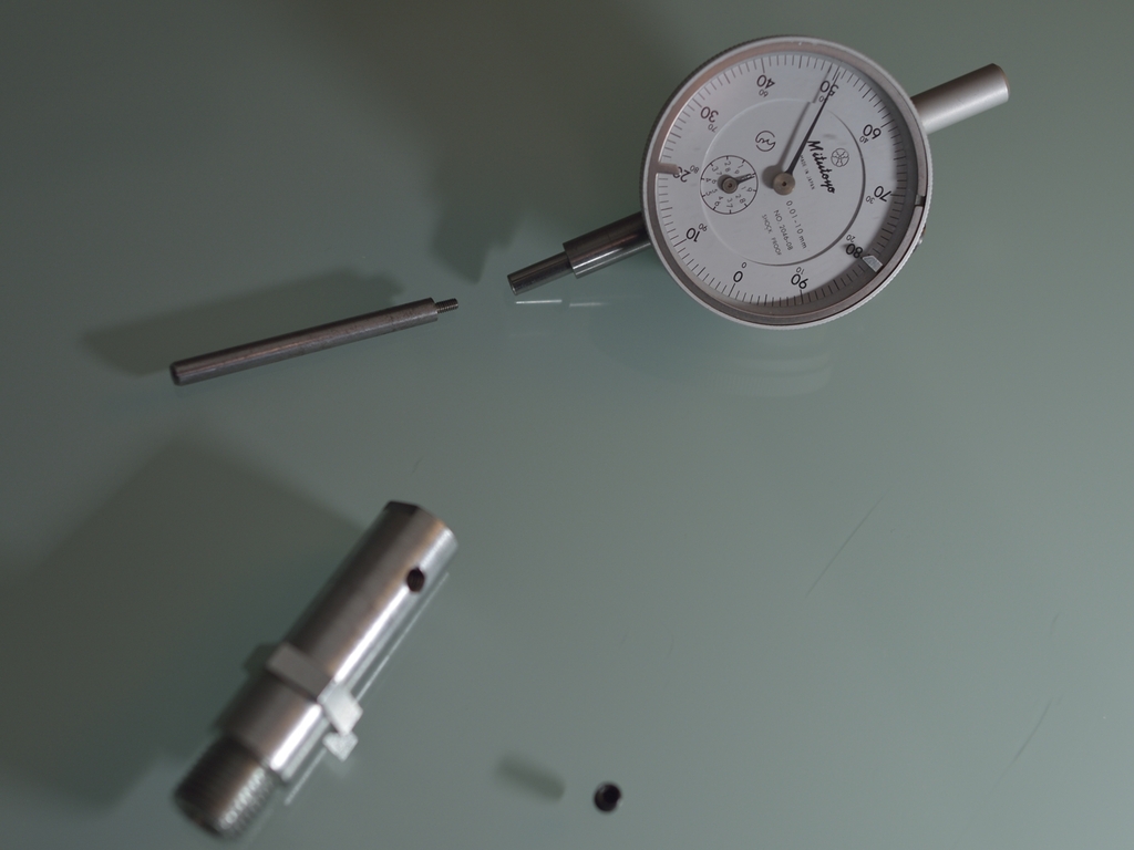
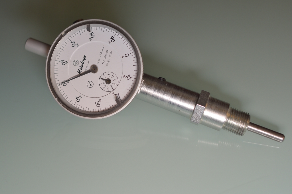
Did a quick try, and it works great. The hole process took me 'bout 40 minutes. It's a great satisfaction to be able to build your own tools, even though you haven't started from scratch.
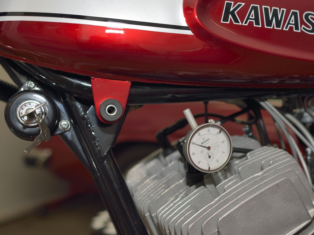
Luckily I've got this to help me... + plus some audio device to indicate when points begin to open. But still a very tedious task, I guess.
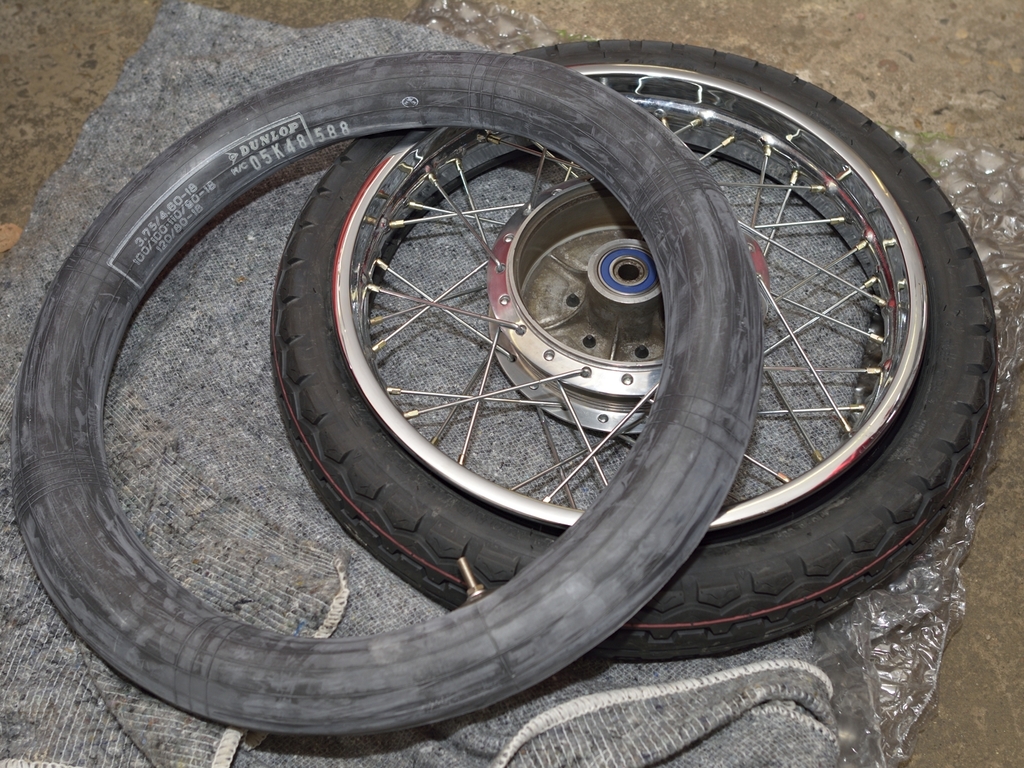
Enough said about tyres, lets see what we can do about them. Rear wheel:
First part is easy. Rear wheel is 4.10-18H and according to what's written on
the wall, you must be aware of direction of rotation.
No fuss getting this far without using tire levers:
I hate tire levers, way too easy to get the tube squeezed btw. tire lever and
rim, unless you are very careful, and you use fingers to feel.
A big tire lever is also very good at making marks in the original re-chromed
Tagasako rims. A new tube of course.
For lack of better knowledge, I use the same approach as when I'm fixing a
normal bicycle:
- I pump a little bit of air in tube, so I remains "straight" when pushed into
tire.
- I start by tighten nut for the valve, so tube is held down to rim. Then I
start working on the bead adjacent to valve.
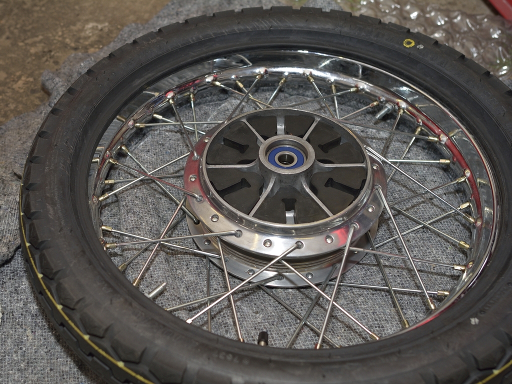
Tube in place now. I liked the look of the bead protectors protruding from rim,
but I dislike the weight of 2 of these things in my rear wheel, so I cut them
into a small piece using a hacksaw,
and then I shaped the rubber so it will be
squeezed tightly to rim, when the nut is tightened from the outside.
This is how far I got without using a tire lever, thanks to wifey's liquid potassium soap:

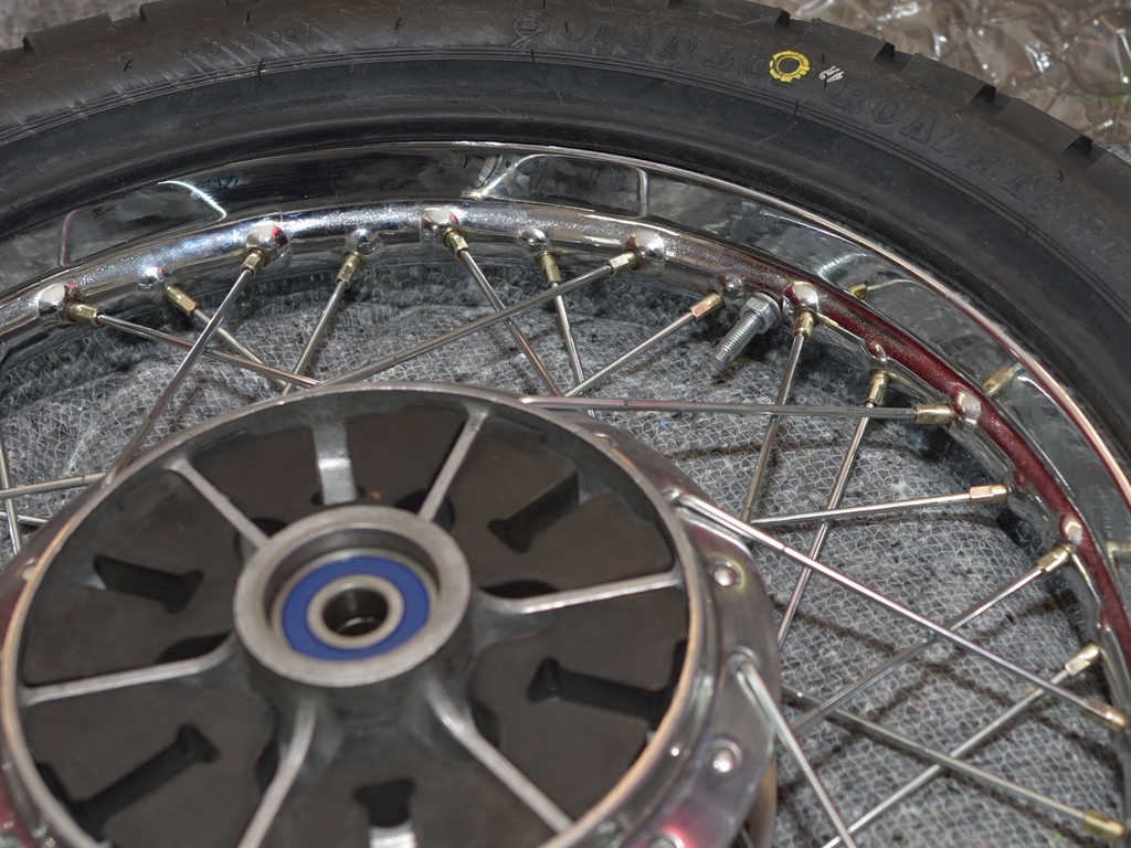
Using a tire levers once close to where the bead is actually in place, will make
you do the last part by hand. Finished.
Same procedure for front wheel 3.60-19 H (which for some reason in NOT uni-directional).
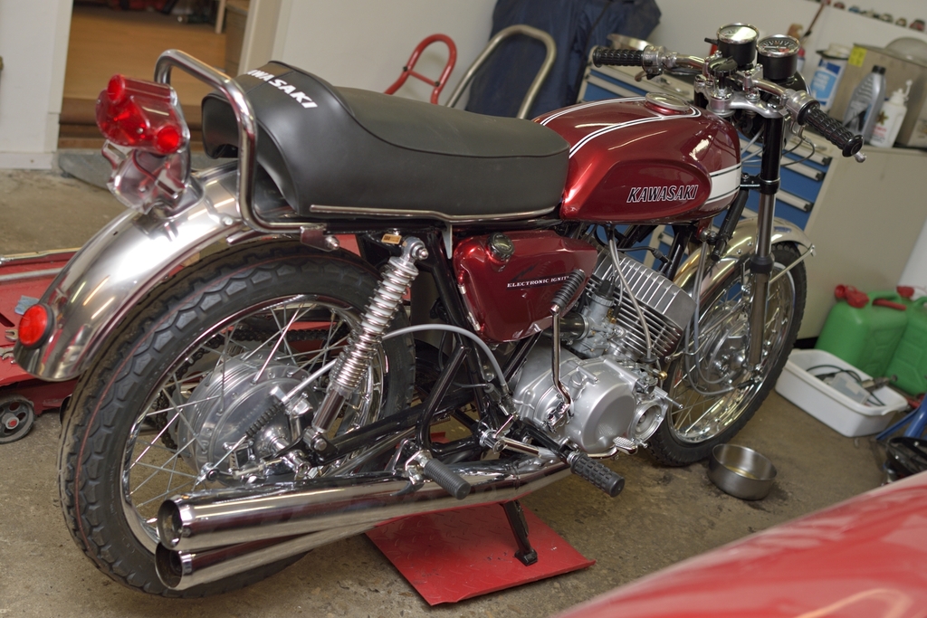
Standing on my own "feet" for the first time in 2,5 years:
My paint shop finally finished the engine covers, and I picked them up Thursday evening after a long cozy chat with the Master himself. And the result:
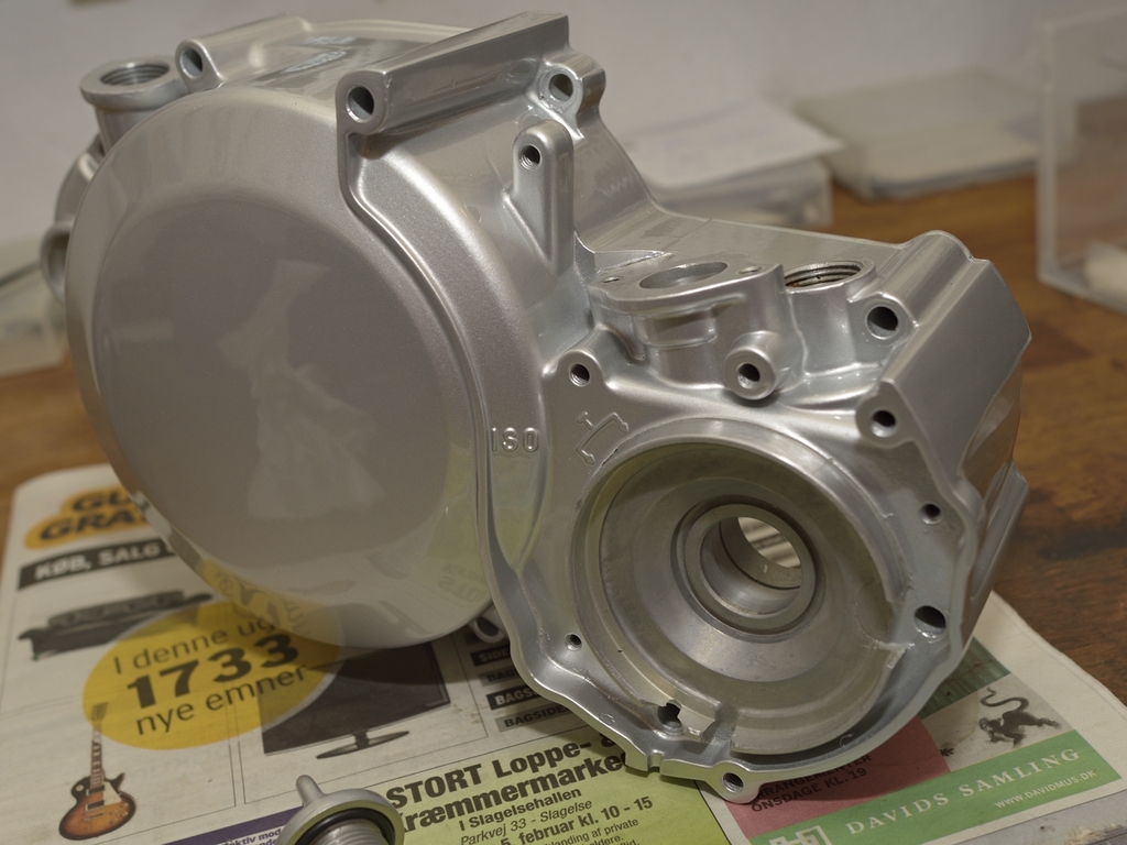
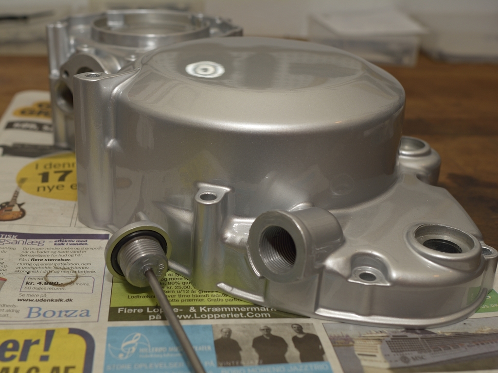
More pics to follow... but definitely worth waiting for, don't you think.
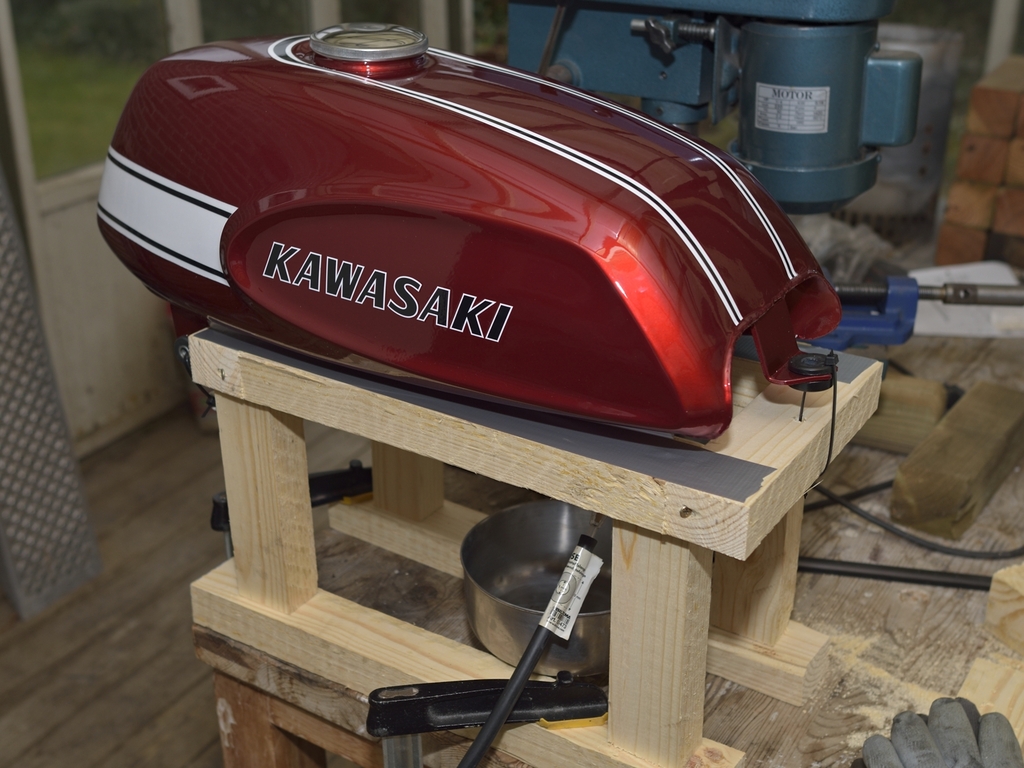
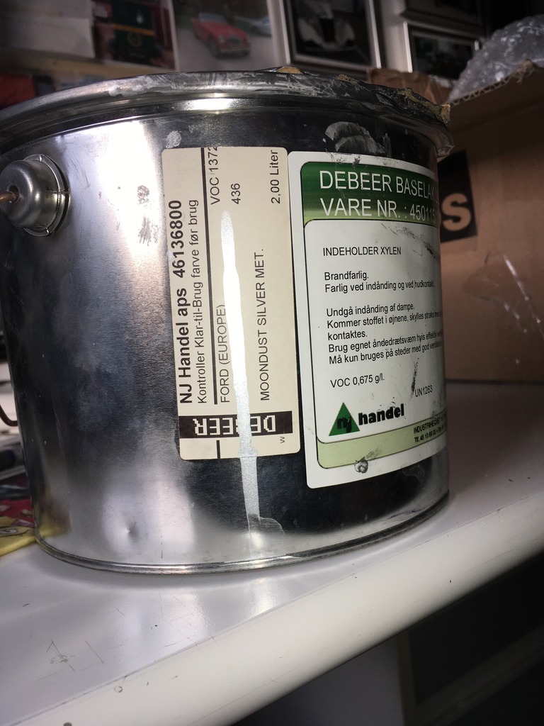
We ended up talking about the colors the used. So for what its worth, here they
are:
First, the silver paint used for engine covers. "Moondust Silver Metallic" its
called. It's an original FORD color.
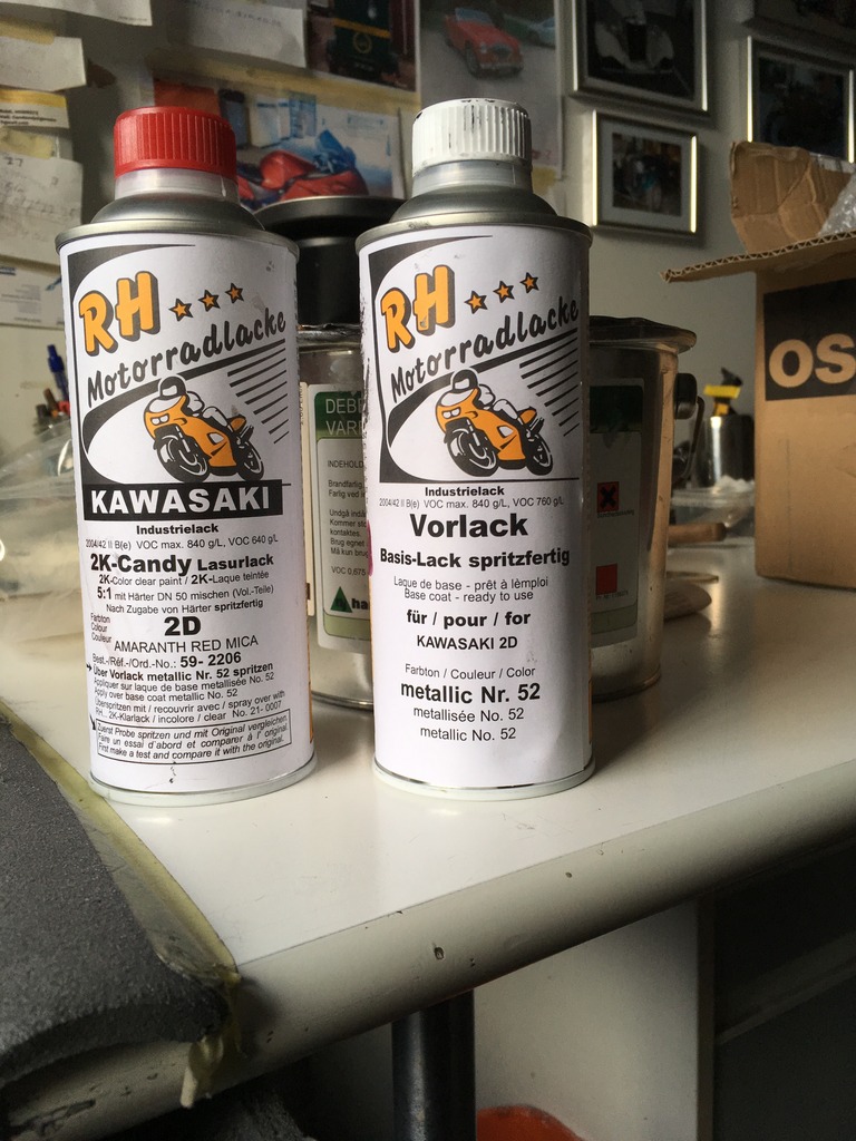
Then the red color and base coat: you've seen the result earlier.
All the engine covers together:

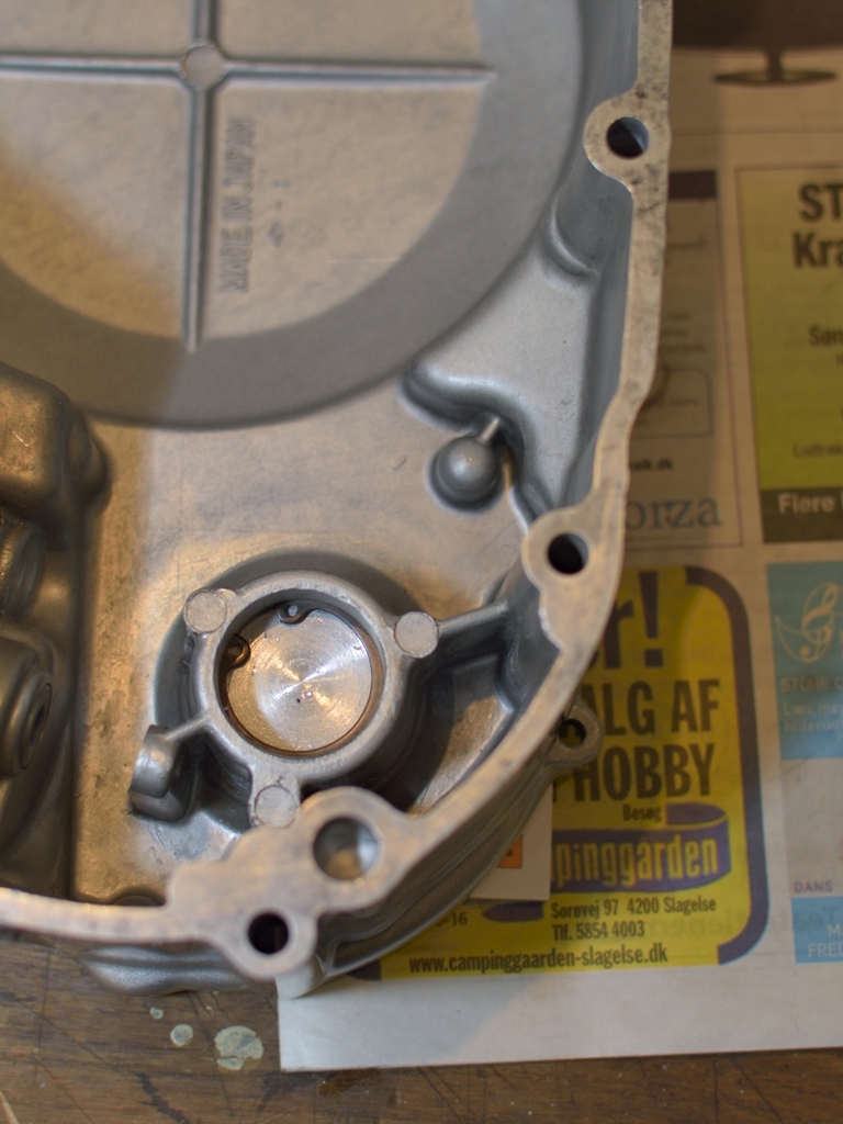
The clutch cover is the one which requires all work after it has returned from painter. As you can see, I'm already started to insert new oil seals into the clutch cover:
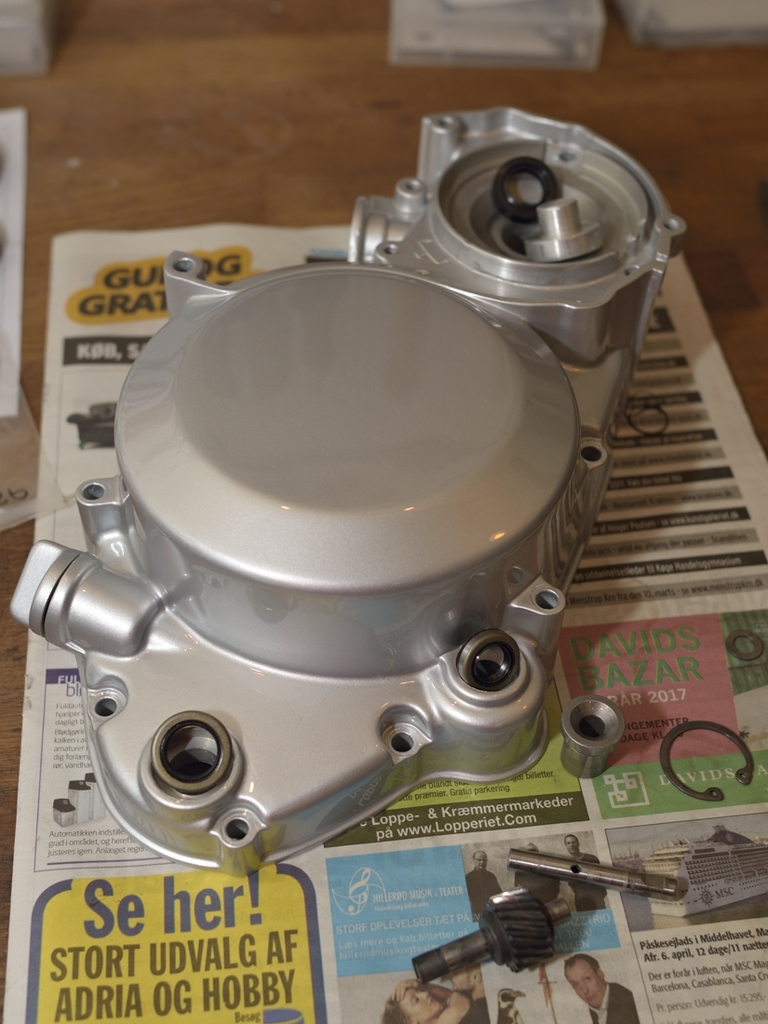
At the rear is the aluminum plug used for blinding the hole for the rotor, as
this is not used on an Euro model.
The casting for the clutch cover is the same,
so an oil seal plus the alu plug must be inserted and secured with a circlip
from the rear.
Oil seal for kick start axle was easy, and so was the small seal for the tacho
drive axle. But of course the one for the gear change mechanism was 0,5 mm
LARGER than the hole in clutch cover
 I have experienced this quite often with non OEM parts. After a few tries with
gently heating of the cover, I binned the seals, and now I have ordered new OEM
parts from France. This seal is 12-20-5 mm, I think and for the fun of it, I
actually found 2 original Piaggio here in Denmark, which I instantly bought, as
they were cheap. They probably come from a Vespa
I have experienced this quite often with non OEM parts. After a few tries with
gently heating of the cover, I binned the seals, and now I have ordered new OEM
parts from France. This seal is 12-20-5 mm, I think and for the fun of it, I
actually found 2 original Piaggio here in Denmark, which I instantly bought, as
they were cheap. They probably come from a Vespa
![]()
So now I have at least 2 more shots ... Inside the clutch cover there are the
drive for the tacho and the oil pump:
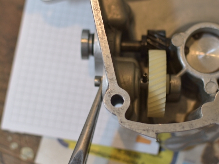
You will need an extra hand to prevent the axle from rotation while you punch in
the small cotter pin which secures the white plastic wheel. I changed this
plastic wheel, as the hub looked a little out-of-shape. Otherwise just a
cleaning of all bits, and ensuring that cotter pin is able to hold.
Do REMEMBER to place the thrust washer underneath each of the two wheels and
change the O-rings too. Then you should be home free
![]()
I grumbled about the oil-seal for the gear change axle being too big, and I had
binned the seals, and ordered new OEM parts from France. And as expected, the
new seals were a nice fit. Thanks Patrick. So what did I learn: Use OEM parts
where you can get them!
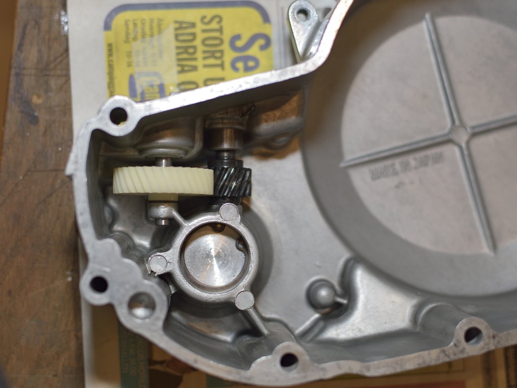
Gear for pump and tacho was already finished
last time I posted, but clutch cover is still not fitted, as I'm waiting for a
NOS clutch basket to arrive from US. Hopefully this will cure the loose basket.
In the meantime I had time to assemble the kick starter:
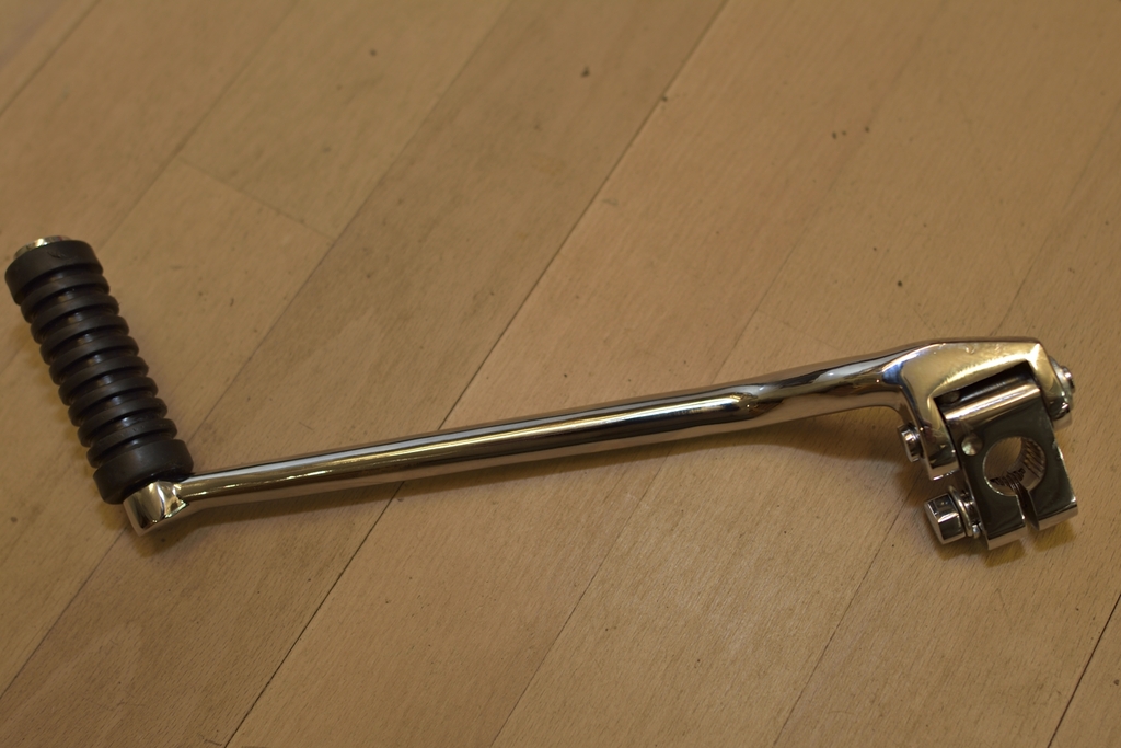
The boss and the arm are not the rigtht one for a 1970 (I've got the right boss)
but the arm which came with the bike, broke close to where it's attached to the
boss. Quite frankly, I don't care.
Have used lots of, lots of time on
getting the cabling right. Apart from tacho- and speedo cables, where the cable
length is independent of choice of handlebar, the other cables needed some
creative thinking to be done when you want to stick to an Euro type handlebar.
But I'm very satisfied with the result now:
Starting to look a little like something.
And not to forget: After hours
of work, double checking and so on, all 3 plugs throw a fat healthy looking
spark, when I kicked the starter.
But I got so fed up by the sound of my
buzzer that I made myself a lamp instead.
You have to learn - by doing - just
HOW small taps it takes to get the timing right, especially for no. 2 and 3 cyl.
Hopefully next time will be a little easier, now the the timing is "tuned in".
FINALLY - after being more or less in limbo since mid february, my NOS clutch
basket arrived last week in Malmø, Sweden!!
As engine has been mounted in
frame since long ago, I had to borrow a Van from a friend and load the
un-finished bike into it. Once again a nice ride to Sweden, crossing the water
btw. Denmark and Sweden.
Well arrived in Malmø, famous swedish Kawasaki
Triples wizard Ebbe Parnestål immediately starts working on swapping the clutch
basket, + adjusting springs and clutch-release:
The result of a genuine craftsmans work in 20-25 minutes: An as-new clutch with
no rattle, and a clutch lever which can be actuated with a fairly normal
pressure. Ebbe has mounted slightly stiffer-than-original springs. And then, all
left for me, is a smooth and easy - 50 miles ride back to Denmark.
Found
out that my front forks are leaking from the small drain screws below. New
screws and gaskets were already fitted, but I'll have to work it over once more.
Almost dropped the bike, when pushing it back into the garage, but I grabbed it.
Phew!
Getting closer and closer: Front brake now adjusted, and lever feels quite firm.
Lotsa good hints regarding how to adjust this brake
here
and
here.
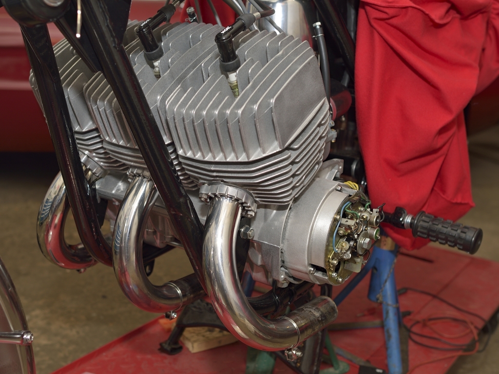
Today, I just made a loose fit for the exhausts, to get an idea of the looks:
Some other details however still needs some TLC:
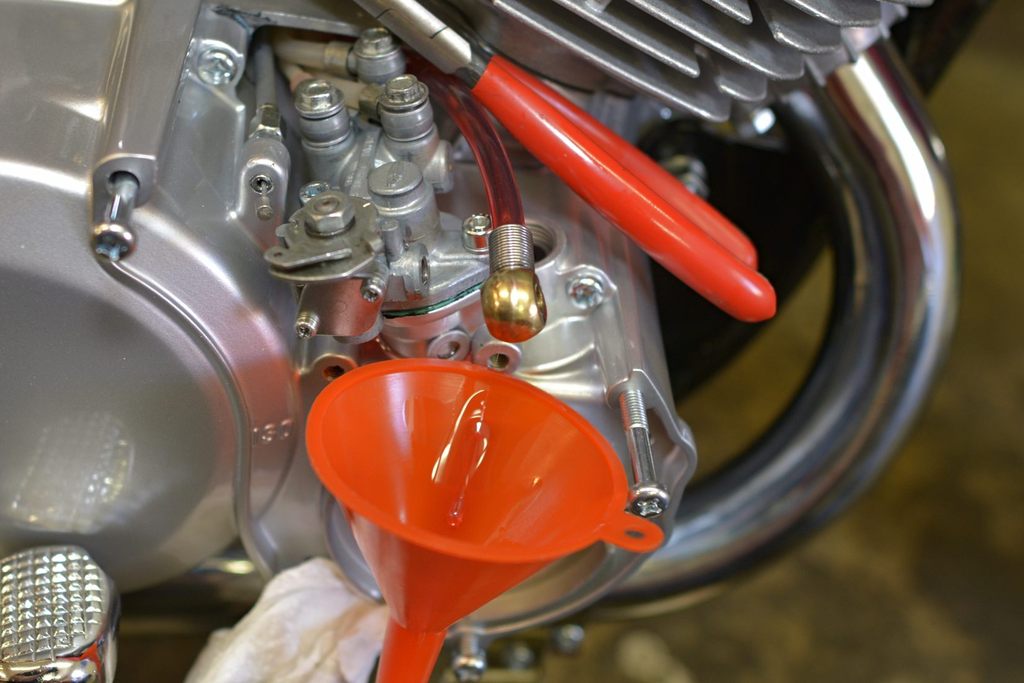
And finally, oil pump and lines need to be primed.
And new oil needs to
filled in forks + new drain screws .... and ??
It was Ascension Day yesterday = off work. Took the day off today, Friday + 2
days during weekend = lotsa time to get all the last small details in place, and
get the bike started. It least that was what I thought!'
With 2 new drain
screws + gaskets, the front forks has stopped leaking oil. This time, I
inspected the holes carefully, and I did apply some LockTite to the screws
before finally securing them with a gentle blow from an impact driver. No leaks!
A small amount of oil was filled into tank, and I noticed, how the oil
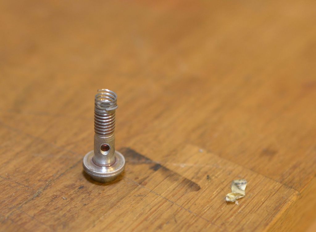
flowed through the main tube, and no leaks anwhere. But when I was to tighten
the biggest of the 4 banjo bolts to the pump, the thread just snapped all of a
sudden! I'm always very aware of not overtighten, and I try not to grip a
spanner at the far end, thus minimizing the torque arm. And my alu washers were
brand new.
Kind of a bummer :(
So I had to drain tank and main pipe
again and this is how the banjo bolt looked when I got it out:
Guess there some good advise to be had
here.
When I removed the pump, I actually noticed that the 3 smaller threads for
the lines to the main bearings, had already been Heli-coiled, but not the big
one. So it's time to get myself at Heli-coil set. Never to late to learn some
new tricks.
next pic 167 see above pg16