H1
Rebuild
as documented by Goldminer on KTOG board
I bought this bike back in 1979 for $400, I rode it
around quite a bit but had a few close calls and a lot of speeding tickets so I
decided to park it for a bit. I even got a ticket for drag racing, but that was
back in the good old days when the cops would just give you a ticket and say
“Don’t do that again” and send you on your way.
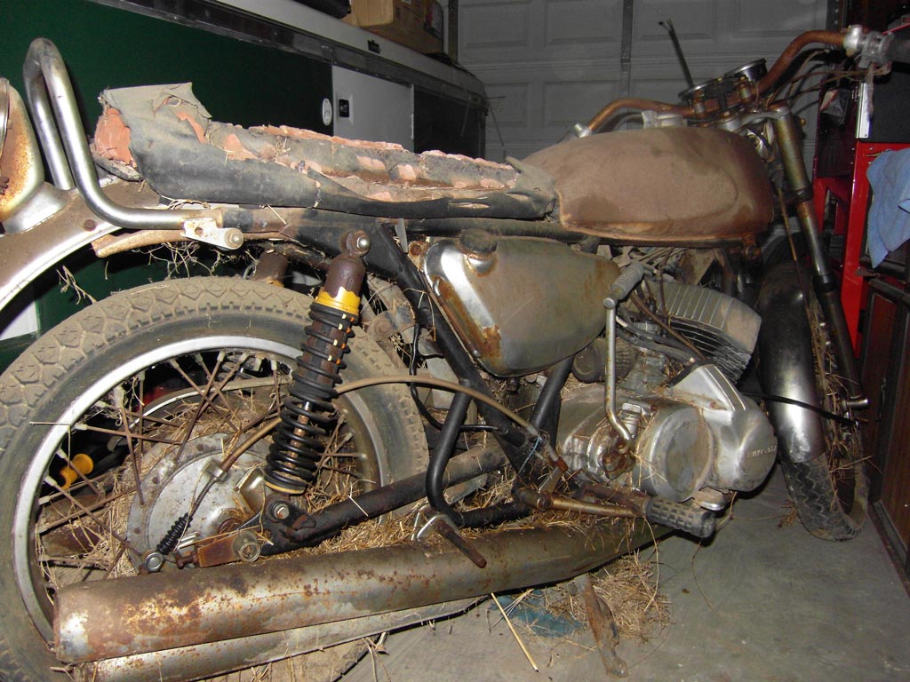
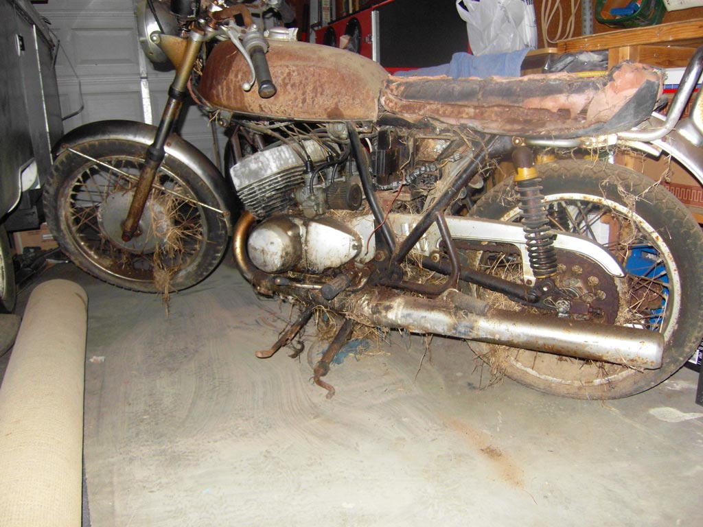
It has been stored in the back yard of my mom’s house covered with a tarp for
way too long. Living in an apartment I had no place to store it or work on it,
so there it sat. I finally got a house with a garage so I decided to drag it
home; I do mean drag it because both wheels were locked up.
I didn’t have the money to restore it so I borrowed it from my retirement
account, you know a couple thousand dollars and a few months and I will have it
back on the road, Yea Right, over $9,000 in parts so far and I am looking at
least $2,000 more. If restoring and riding this bike does not cure my midlife
crisis nothing will.
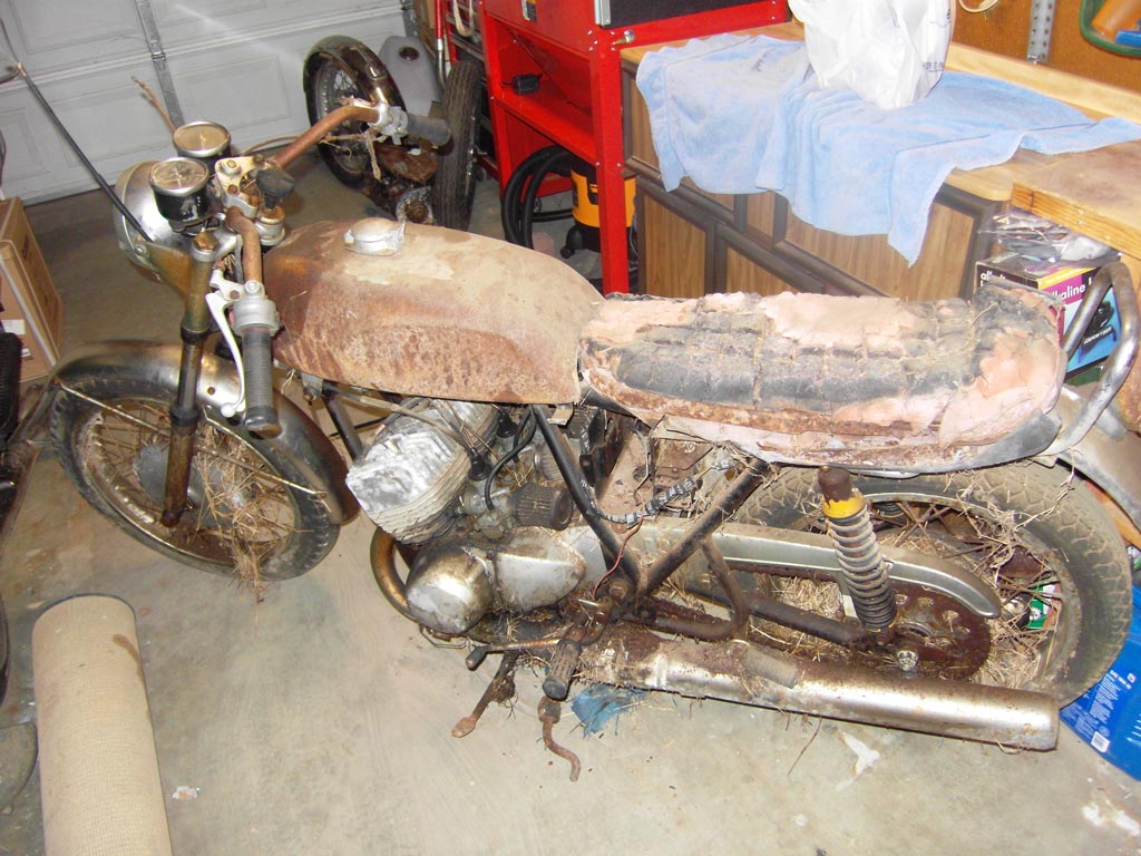
I hosed the bike down with PB Blaster and let it sit for a week. The missus now
gave the bike a new name, “Old Stinky”.
So I started taking it apart and everything went smooth until I got to the
engine. I could not remove the exhaust header collar from the left cylinder so I
disconnected the muffler and was able to turn the header enough to clear the
frame to get the engine out.
Once up on the work bench I tried to remove the cylinders but all three were
stuck so I filled up the head bolt holes with PB Blaster and let it sit for a
day and they still would not come off so I made a press to pull them off.
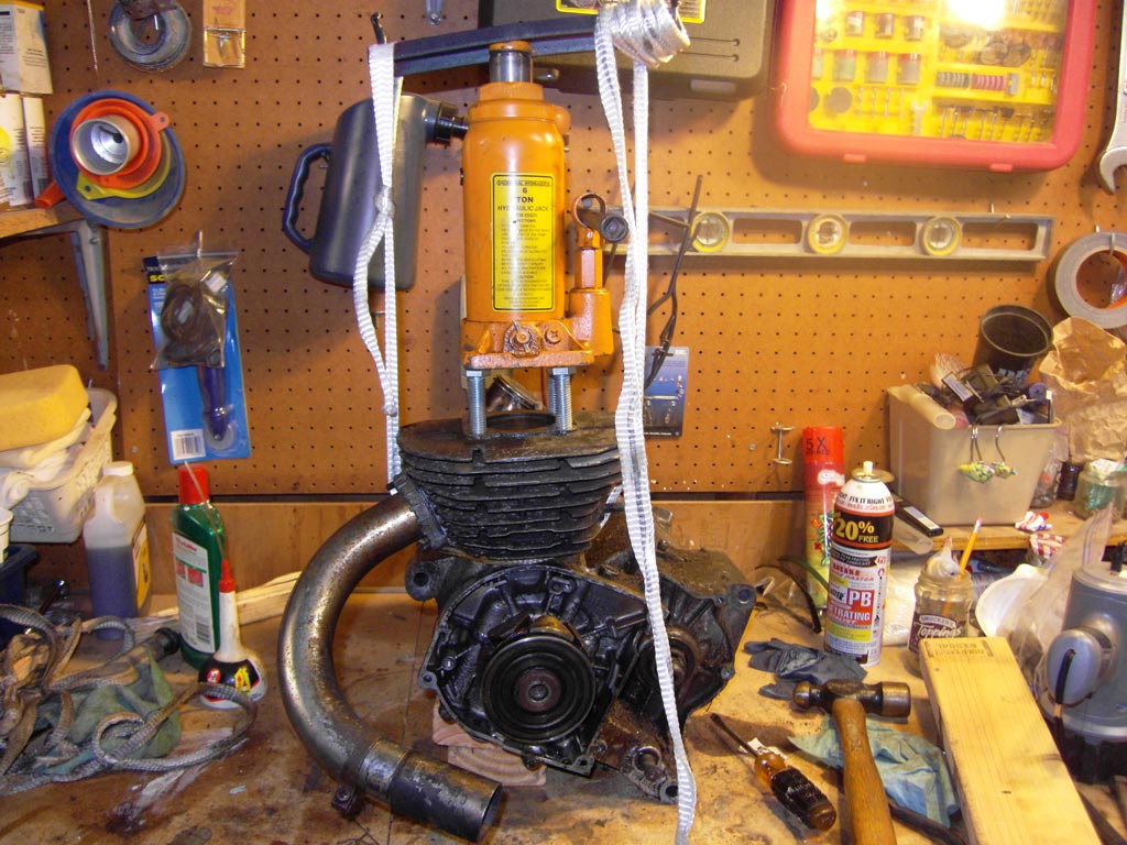
The right cylinder was a little stubborn but finally submitted, the center
cylinder came off with no complaints, but the left cylinder would not come off.
For almost a month I tried everything including PB Blaster, WD 40, carburetor
cleaner, Liquid Wrench, parts cleaner, WD 40 penetrating oil, vinegar, Evapo
Rust, and even a special concoction of acetone and transmission fluid, all
followed by heat from a pencil torch until it bubbled and it still would not
come off.
It was time to stop messing around and break out the big guns, yes Phosphoric
Acid. That’s the active ingredient in Naval Jelly and other rust removal
products. They don’t sell that stuff in California so I had to mail order it.
When it finally arrived I put on long sleeve clothing, rubber gloves and a full
face shield and had a cup full of baking soda (Neutralizes acid) standing by
just in case of an accident, unfortunately I would need it.
I made up a small batch of acid diluted with 50% water in a small bowl and
dropped in an exhaust header collar and the rustiest bolt I could find and
fifteen minutes later the bolt looked brand new. After thirty minutes of soaking
there were no adverse effects to the exhaust header collar or the bolt so using
a syringe I squirted some down the head bolt holes. About fifteen seconds later
my hand starting hurting, I looked at the glove and there were no holes in it so
I peeled back the glove and to my surprise my hand was covered with blood. I
quickly removed the glove poured baking soda onto the top of my hand and started
rubbing it into my hand and then washed it off to reveal two holes in the top of
my hand. Needless to say the next day I bought some chemical gloves.
After tending to my hand I went back to the engine that had been sitting for
about thirty minutes and sprinkled some baking soda down the holes and set up
the press and it still would not come off. The next day I let it soak for two
hours and still no go, the next day I tried full strength and let it soak for
one hour and it looked like it might have budged a hair. The next day at full
strength I let it soak for four hours and it started to move, using a rubber
mallet I hit up on the header and down on the top of the cylinder over a hundred
times and it finally came off.
Now onto the stuck header, I cut off the header so about an inch was left and
cut slits into the pipe and the collar and the same on the inside of the pipe
being careful not to cut into the port and then using a punch I pounded the slit
inside the pipe until I could see the copper gasket and started knocking off the
cut pieces of the collar until it popped off.
Now onto the locked up wheels, I poured Evapo Rust into the vent on the rear
wheel and used a pump type oil can full of Evapo Rust I filled up the front
wheel though the return spring hole and after two days of wrestling with the
wheels they came apart.
To be continued.
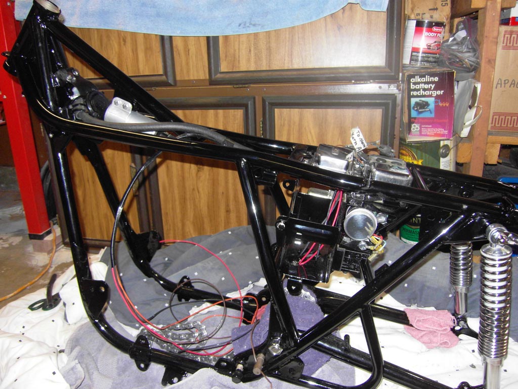
I tried to paint the frame myself several times and things did not go right. I used super jet black urethane acrylic single stage paint and being an amateur I could not get the quality of finish that I was looking for. From what I understand the clear coat is mixed into the paint and as the paint dries the clear rises to the surface so if you have any issues and try to sand it you end up sanding off the clear. I finally gave up and had it powder coated gloss black.
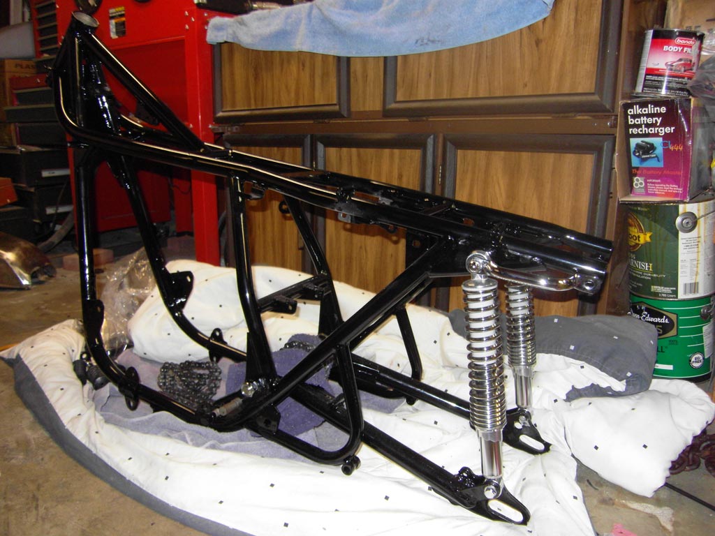
I installed a new polished x-ring chain, new bronze swing arm bushings, new
swing arm sleeves, new swing arm O-rings and a new swing arm nut. Next came the
new reproduction shocks and new shock bolts and nuts and a NOS grab handle.
Notes:
Chain: I had the local Kawasaki shop rivet the chain and had to loop the swing
arm through it before installing the swing arm.
Swing arm: I took the swing arm into the house to warm it up to get it to
expand, and put the bushings in the freezer to get them to contract to ease the
installation of the bushings. Packed lots of high temperature disc brake grease
into the swing arm.
Grab handle: I dropped off the original grab handle at the chrome shop and will
install it on the other side; I think the passenger can hang on to the handles
but I am not sure.
Bolts: I used Anti-Seize on all the bolts.
Comments: I don't know if this would matter to you, but in regards to your shocks, for the 69-72 H1's, the shocks actually appear more like these, having approximately 3 closely wound coils at the bottom as opposed to the ones you show.
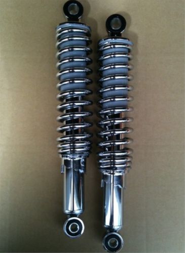
Also - the very early '69 H1 shocks have a "sand cast" adjuster at the bottom - they are getting hard to find....
Looks like I was sold the wrong parts again. I am trying to improve the handing, such as bronze swing arm bushings and roller bearings for the steering stem. So it is probably best that I get the right shocks. I bought these shocks over 30 days ago so I can’t send them back so I guess I will just add them to my ever growing pile of wrong parts.
I would like to get as original as possible on the
reproduction parts but right now one of my goals is to increase my life span
when riding my bike by improving the safety of the bike. I plan on doing several
modifications to the bike that will be completely reversible.
It looks like I have a numbers correct bike, the frame number is 10 lower than
the engine. I agree with most of you whether it be a car or motorcycle, if the
numbers match, keep it original, if not it is ok to modify, but again everything
will be completely reversible.
I will be uploading a post in the next few days showing one of the
modifications.
Install the battery box, rectifier,
voltage regulator, box A, box B, dual air horn and compressor and coil using
polished stainless steel bolts.
Notes:
Bolts: Did you know that there are over 500 bolts, screws, nuts and washers on
this bike. I am replacing most of them with stainless steel. There are a few
special bolts that I am using NOS bolts that have a rounded head edge, like the
handle bar clamps, gas tank and the triple clamp. I will be using the original
sprocket bolts because they are high strength bolts. The stainless steel bolts
that I got have raised lettering so I have to grind off the lettering and then
sand off the scratches them buff to a mirror finish. I will be using anti seize
compound on all bolts.
Comments: Might I suggest blue Loctite?
I was thinking about using Loctite because the bike
vibrates so much but was not sure if I can use it with anti-seize. I was reading
that you should use anti-seize on stainless steel bolts plus the powder coating
guy cleaned all the bolt holes and it looked like they were starting to rust and
from what I can tell the anti-seize is some kind of lubricant.
Maybe I could use anti-seize on the bolt and screw it in then remove the bolt
and clean it and put Loctite on it?
Comments: Threads have to be absolutely clean
of anything oil based. You anti-seize things and the bike will fall apart right
underneath you. The only fasteners you really could benefit using anti-seize
would be the 12 cylinder studs shanks, as well as the outside shanks of the
cylinder head bolts, to prevent future corroding and seizing. I also use a thin
film of it on gasket surfaces that have a tendency to stick, such as intake
manifold, clutch cover, and cylinder base.
Thanks everyone for your comments.
I will pick up some blue Loctite tomorrow. I was thinking about spraying
carburetor cleaner on the bolts and in the bolt holes to remove the anti-seize
compound. I have 12 new cylinder studs and will use the anti-seize on them.
Battery Box: to insure proper grounding I removed paint from the upper mounts on
the battery box and on the corresponding locations on the frame and on the frame
horn bracket and used gloss black enamel model paint to touch it up.
Electronic Components: Tested the rectifier, voltage regulator and box A. if you
are using an analog ohm meter it will work fine when testing the rectifier, but
a digital meter may not work using the ohm function so you must use the diode
function, at least on the cheap meter that I was using, took me a couple of
hours to figure that out.
Air Horn: This is a 118db dual air horn and let me tell you this sucker is loud.
If you try to cut me off or pull out in front of me you better be wearing a
diaper because when I hit the horn it will scare the crap out of you. It is
almost completely hidden, if you squat down you can just see the bottom of the
horn under the gas tank. This modification is completely reversible and a must
for me. I have been run off the road, pushed into oncoming traffic and cut off
so many times I have lost count and the wimpy stock horn is pretty much
worthless, now this is what I call a horn. What a project that was, took me over
2 weeks and was like trying stuff 20 pounds of potatoes in a 10 pound sack. If
anyone is interested I will start another thread on this modification, not sure
what topic to put it under.
Coil: The coil needed to be installed backwards because the air horn was in the
way, I haven’t installed the main harness yet but it looks like the wires are
long enough to reach the coil.
I just got some new fork tubes for my 69 H1 from Z1 parts and it only has a small hole where as the old tube has a small and large hole, so it looks like I need to drill a hole. Just wanted to check to see what you guys think before drilling, thanks.
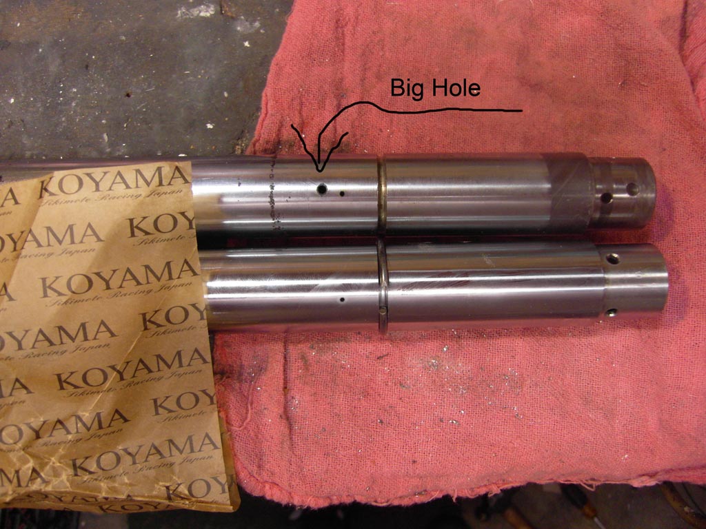
Comment: It appears someone may have added the
big hole, judging by the rough surroundings. My guess is these holes effect
rebound damping in the early forks..
Normally the rebound holes are modified to a smaller size as a handling
improvement in the later forks (to increase the rebound damping)...
FWIW, My suggestion is to NOT drill any additional holes in your new tubes..
Yea, I was thinking the original owner drilled out the holes in the fork tubes as he also added 1 inch springs to the front end. I leave the fork tubes as is and will try it with the extra springs and if it is too firm I will take them out.
| firefour1 wrote: |
| On the new fork tubes you purchased from Z1, did they send new lower bushings that fit on the bottom end? If not, how did you remove the old ones with the pressed in locking pins? Am about to order tubes from Z1 but cannot be sure how to take the old ones apart. |
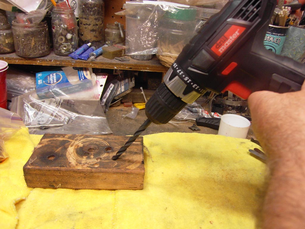
The problem is after drilling the final size the bottom of the hole is cone
shaped and the pin did not go in deep enough and I did not want to go too far so
I had a spare bit that I ground the tip flat so I could drill out the cone part.
Lots of work but little progress so it seems. Took the bike apart and cleaned the anti-seize off the nuts and bolts using spray carb cleaner and used Loctite on all the bolts. Dropped off some parts at the chrome plating shop and a month later picked them up.
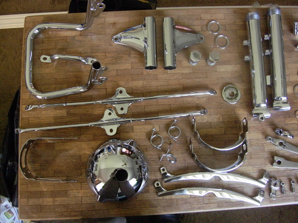
After comparing the quality of finish of the NOS parts that I bought they were not up to par with re-chromed parts so I decided to get them re-chromed plus a few more parts, but this time it took 6 weeks to get them back.
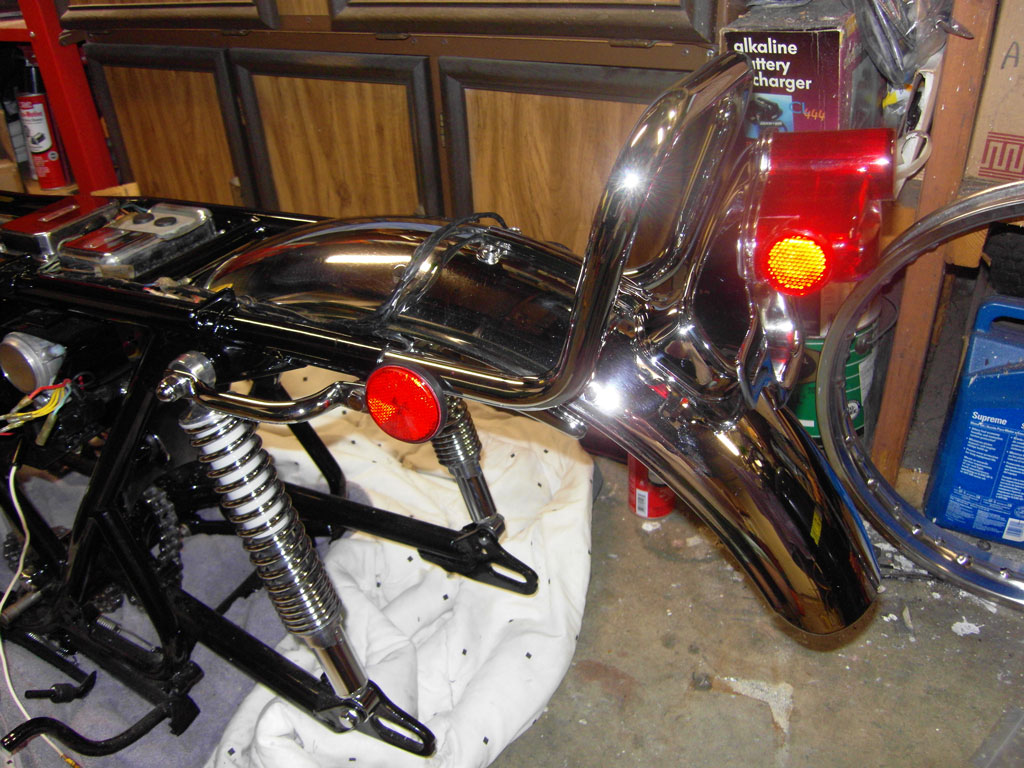
I polished up and installed the rear fender with new grommets, stainless steel
nuts and bolts with Loctite, rear fender stay, tail light assembly, reproduction
lenses and gasket and new light bulb. My bike did not have reflectors so I
installed LED reflectors that are the same size as the original but has 24 mini
LEDs. Hopefully this will increase my life span when riding the bike.
Notes: The fork covers should be silver and the rear fender brackets were black
but I had those chromed. For the LED reflectors I made a little bullet connector
jumper and connected it to the tail light. I bought a real nice connector kit
(Model CK-1) at
http://www.vintageconnections.com and it is made for Japanese vintage bikes
and comes with a professional crimping tool that make a crimp that looks like
the top of a M not like those cheap crimpers that make a flat crimp.
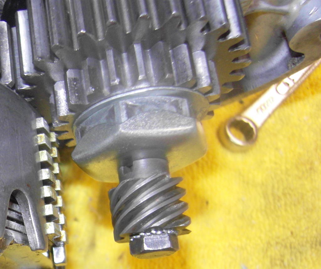
The drill I am using has a no load speed 900 rpms so I figure that with a slight
load it should be spinning at about 850 rpms. According to Darth the crankshaft
to oil pump gear ratio is 2.5666 to 1.
| Darth wrote: |
| I determined that the crank to oil pump ratio is
somewhere near 2.5666:1. 2.56 turns (revolutions) of the crank to 1 turns (revolutions) of the pump. Darth |
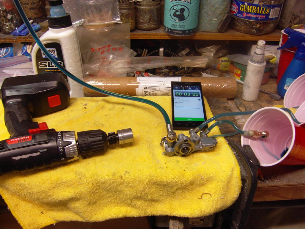
I put a funnel on the end of the input oil line and attached a string from the ceiling to the funnel and filled it up with 2 stroke oil and run the pump to fill up the oil lines then put cups under the ends of the oil lines and ran the test for 3 minutes with the oil pump wide open or close to it, the oil pump lever was turned 90 degrees from the stop position. I ended up with just a tad more than a teaspoon or about 5cc of oil per line.
Lot of hours and lots of Loctite. I kept setting the
Loctite on the ground and forgetting about it I would usually end up accidently
stepping on it and popping it like a zit, I should at least put the cap on to
give it a fighting chance.
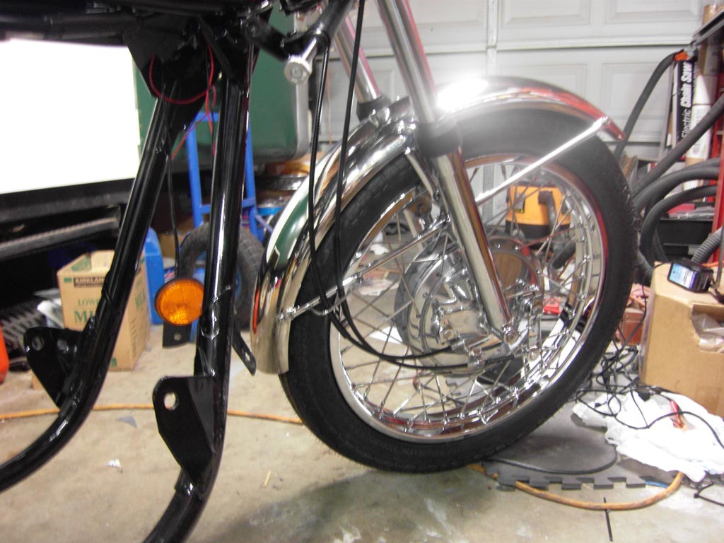
New tire, tube and tube protector. New DID rim and stainless steel spokes. New
Vesrah brake shoes and new brake springs. New wheel bearings and seals. Polished
up the front hub and re-chromed the brake cam levers and linkage.
New reproduction rear brake cable, speedometer cable, tachometer cable, clutch
cable, throttle cable, starter cable and front brake cable. New reproduction
main wiring harness. New Absorbed Glass Mat battery.
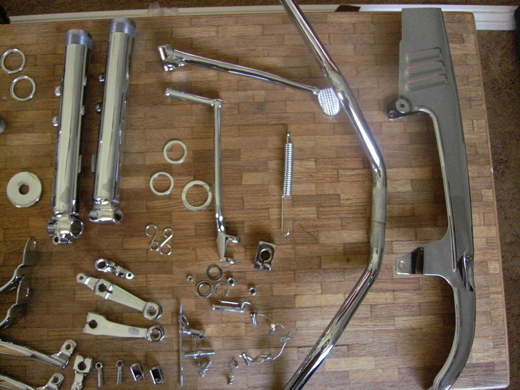
Polished up the front fender and re-chromed the struts and bracket and used
polished stainless steel pan head screws. Re-chromed the fork lowers with new
drain screws with gaskets. New fork tubes with dust boots, new fork seals and
new O-rings for the re-chromed fork nuts and new O-rings for the re-chromed top
fork bolts.
Upgraded the steering stem bearing to tapered roller bearings. Reproduction
steering stem nut, reproduction steering dampener knob and new steering
stabilizer.
New grommets for the re-chromed handle bar clamps with chromed bolts. New
grommets for the speedometer/tachometer bracket and had the gauges rebuilt by
Don Fulsang. He does good work and you can find his contact info on this site
under Sales and Service.
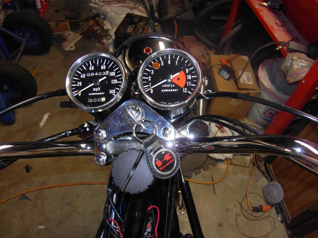
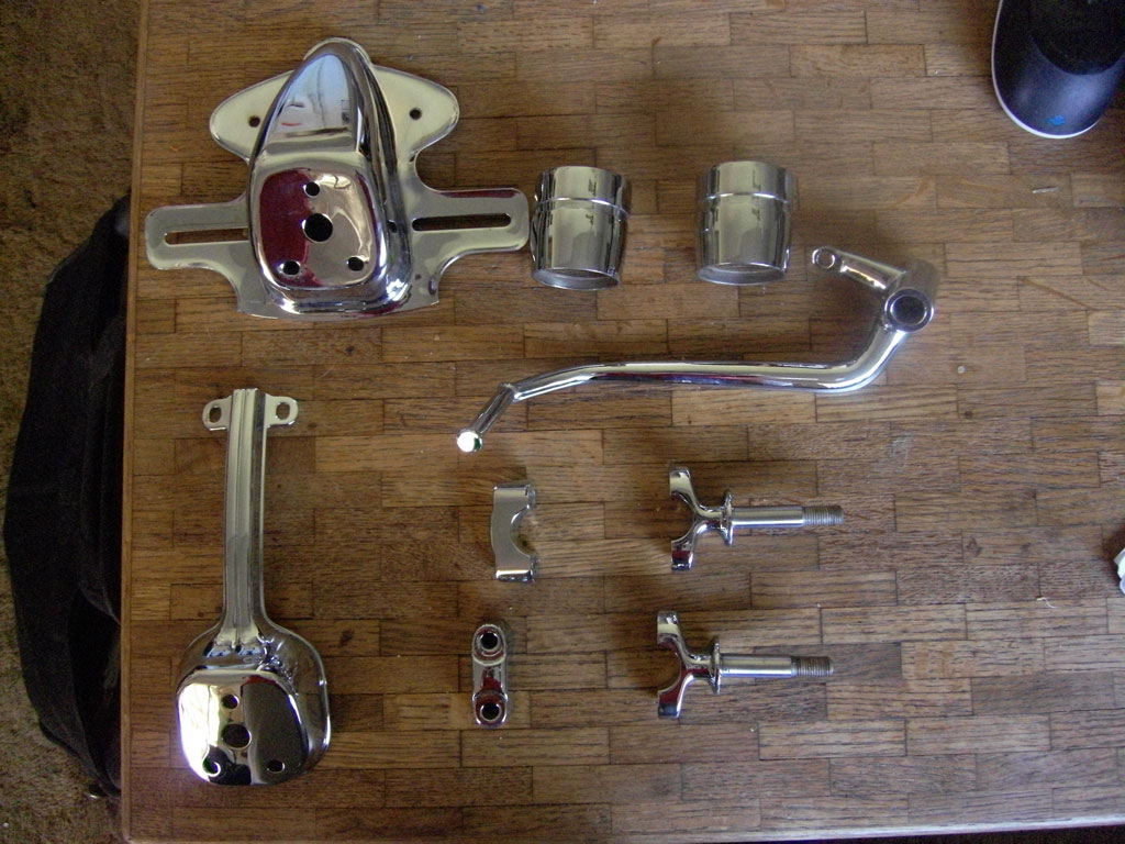
Re-chromed the fork covers with new gaskets and re-chromed head light bucket
with new rim and a metal halide light. Re-chromed handle bars with new grips.
New upper and lower left handlebar control with new harness, horn button and
turn signal knob. Wired up the LED reflectors and got them just hanging until I
install the gas tank.
Notes
Metal Halide Light: Also known as a HID light or more commonly known as a xenon
light. Ok, I know what you’re thinking, but hold on there and hear me out before
you judge me. Now xenon lights have got a bad reputation because of blinding the
oncoming traffic because of improper installation. Some people get a conversion
kit with a bulb that has a high color temperature that puts out a blue light.
They think the blue light looks cool and don’t care about blinding oncoming
traffic.
The best way to go is with a projector.
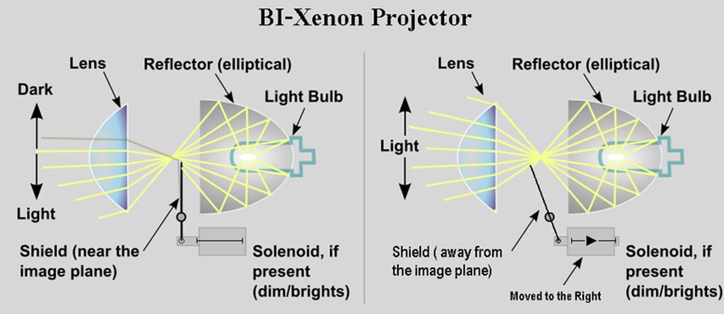
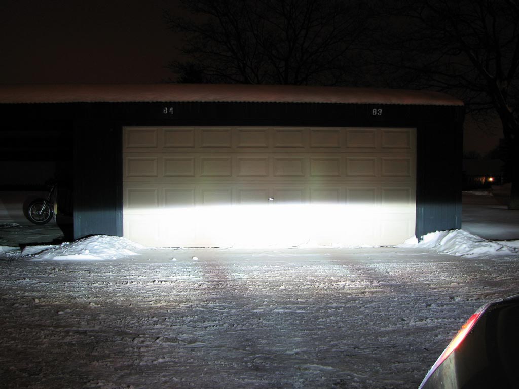
A projector consists of a reflector, shield and a lens. In the low beam position
the shield blocks half of the light creating a light cutoff point, below the
light cutoff point there is light, above the light cutoff point there is no
light so you won’t blind the oncoming traffic. Here is a picture that I got off
the internet showing the light cutoff.
When you switch to high beam a solenoid lowers the shield and you get full light
coverage. The problem I had with a projector is that they are 6 inches long and
I only have 3 ½ inches from the headlight glass to the back of the headlight
bucket.
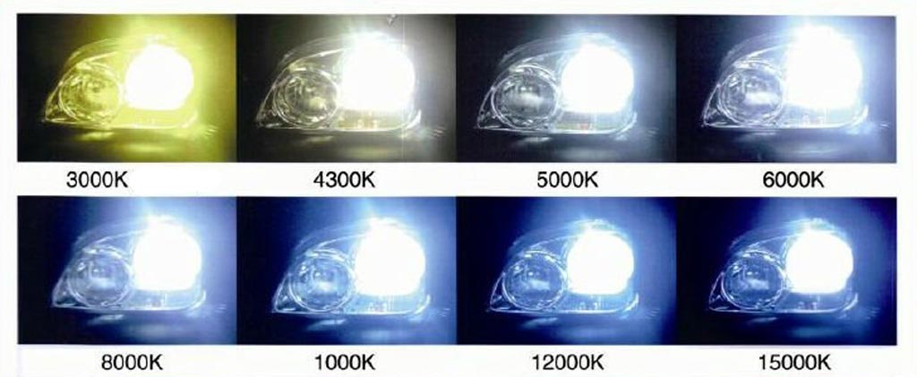
The second best way to go is with a shielded bulb. So I found a kit that has a
shield around the bulb. The OPT7 AC Slim Hid Kit H4 Bi-Xenon 5000k is a real
nice kit. It has a AC ballast that is more efficient and stable than the cheap
DC ballast and has a color temperature of 5000 kelvin. The 4300k light has a
tint of yellow and the 6000k has a tint of blue and the 5000k is the goldilocks
bulb, just right.
This OPT7 kit is rated at 35 watts, but that is the output, and if I did the
math right it should have about 42 watts going into the ballast after the bulb
has stabilized, but during startup it is going to suck about 120 watts so using
the included relay is a must.
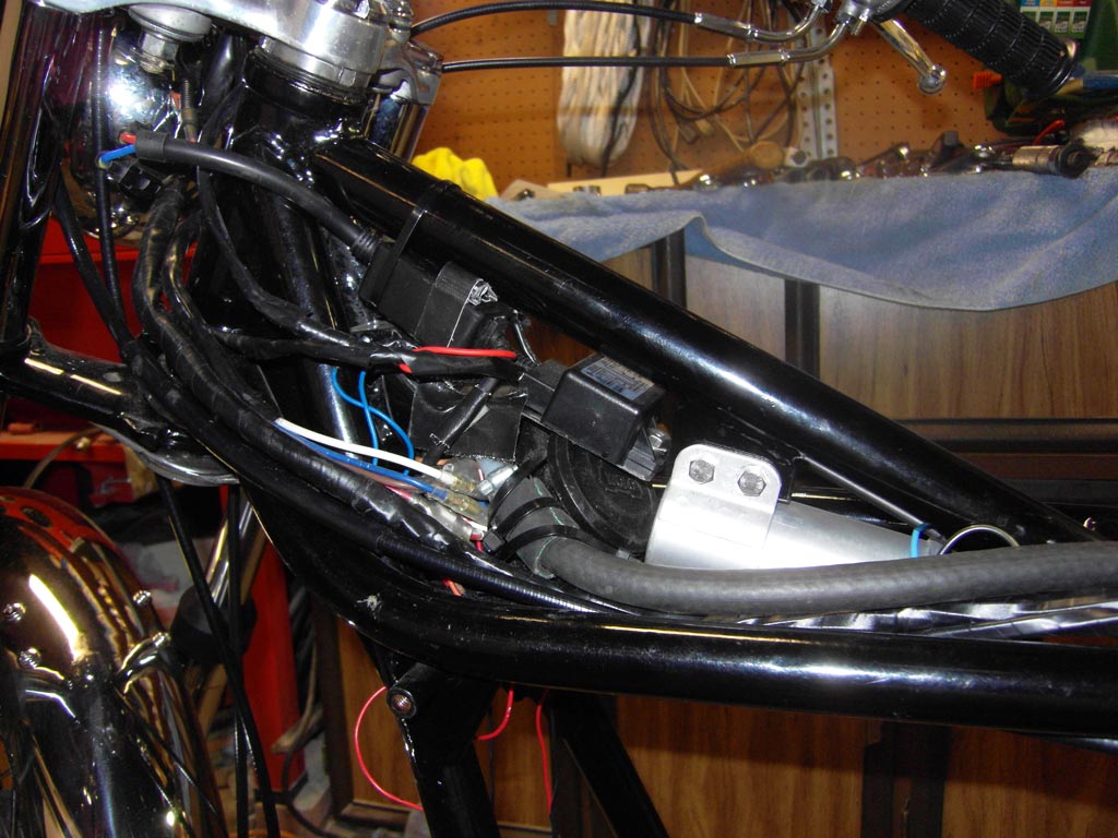
I had to do some creative wiring by running a dedicated fused power and ground
wire coming from the battery going to the relay. There was an inline fuse near
the relay that I relocated to the battery box so if I blow a fuse I won’t have
to remove the gas tank to replace the fuse.
So now I needed to stuff the ballast, a relay control box and some other box (I
think it’s an anti-flicker unit) under the gas tank. It was like trying to put
20 pounds of potatoes in a 10 pound sack, unfortunately the sack was already
full with the 118db dual air horn. Trying to cram all that stuff under the gas
tank turned out to be one of the greatest feats in engineering history.
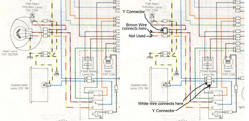
I also had to do some more creative wiring on the high/low light switch wires. I
cut off the H4 three spade connector that is on the xenon kit and grounded the
blue wire that went to the H4 connector (Ground) to the horn bracket bolt and
extended the white wire that went to the H4 connector (Low beam) to a bullet
connector Y that I made up that is connected to the main harness blue wire and
the other part of the Y has the blue wire that goes to the left handlebar
control.
The other wire that went to the H4 connector is a Brown wire (High beam) and
that goes to another bullet Y connector that I made up that plugs into the
red/black wire coming from the left handlebar control and the red/black wire
coming from the high beam indicator light. The red/yellow wire coming from the
left handlebar control is not used.
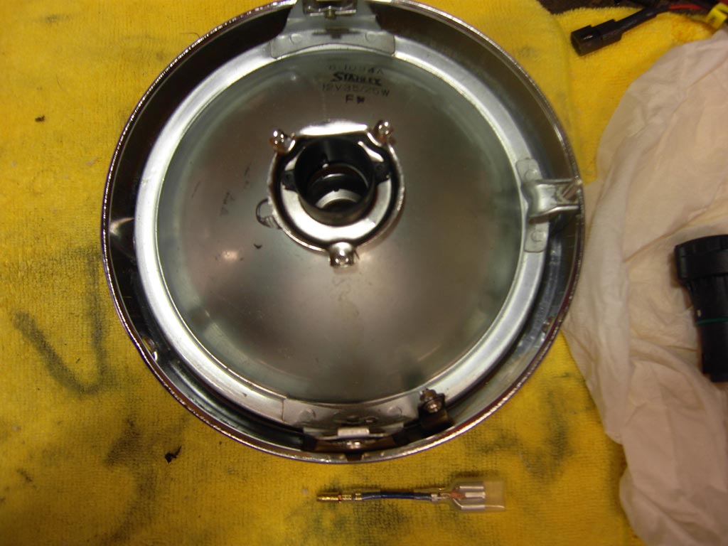
I did not want to ruin the original rare non sealed beam headlight so I bought a
sealed beam headlight and cut off the light bulb and enlarged the hole a little.
The shield had 2 screws at the base so I cut 2 notches in the headlight so the
shield would sit flush.

The shield is glued into the headlight using epoxy resin and is rotated counter
clockwise just a bit to make the light cutoff dip a little on the left side. In
countries where you drive on the left side of the road you would want to rotate
it clockwise a little to make the light cutoff dip a little on the right side.
Horn Button: The manual says the part number for the horn button is 27010-1009
but it was too big, so I found the part number 46028-003 is the right one
Brake and Clutch Perches: The original owner replaced the perches with these
ones from a Honda; I like how the mirrors attach to the perches like on the
later years.
Front Brake Cam Lever: I went to install the cam lever and it wouldn’t go on,
after closer examination the splines were damaged. So I found a NOS one in the
UK and after I got it I had it re-chromed.
Steering Stabilizer: From what I understand this was a dealer installed option
in 69. On my bike the bracket is welded to the gas tank bolt hole. I don’t know
if the dealer installed it of if the original owner did.
Fork Tubes: The original owner added 1” springs on top of the original springs,
so I will try it and see how firm it is. Installed Bel Ray 15w fork oil.
Fork Covers: The original owner chromed the fork covers and I think they look
better than being painted silver so I had them re-chromed.
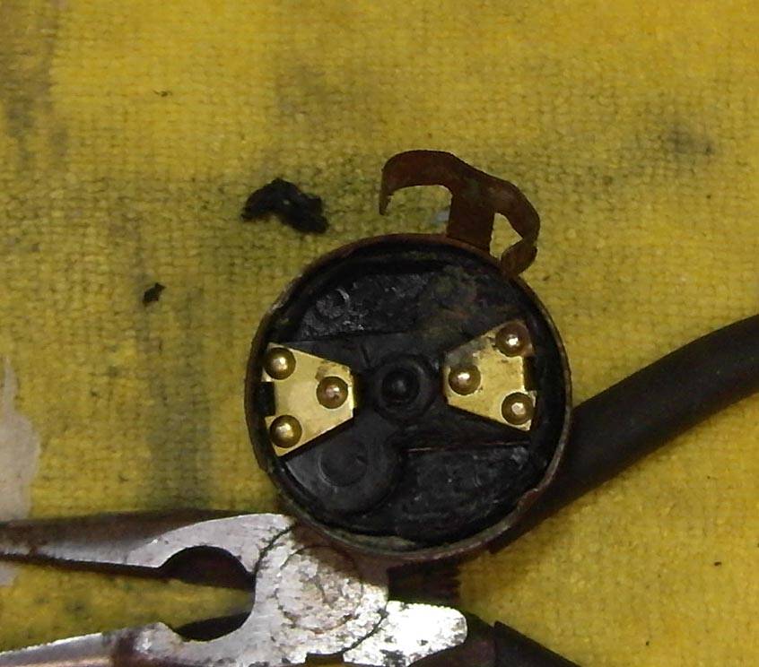
Ignition Switch: When I tested the electrical system the ignition switch didn’t
feel right, it didn’t click right when I turned it on. Then I started seeing
what looked like smoke coming from the headlight bucket, I thought it might be
steam because the day before I had washed out the inside of the headlight, then
I started seeing smoke coming from the main harness and from the battery box.
I turned the key off but everything was still on. I try to remove the fuse and
the fuse holder was real hot and the fuse would not come out. I ended up
breaking the glass on the fuse and the ends of the fuse were welded to the
contacts. I took apart the ignition switch and it look like one of the contacts
was shorting out against the housing.
Because the ignition switch is on the rubber mounted handlebars when the
ignition switch shorted out it was looking for a ground and it found one, right
through my new front brake cable and it fried it good and ended up welded the
cable to the jacket.
I was worried that it may have damaged the fork tubes because the current must
have flowed up the forks. After I got another front brake cable I was able to
test the forks and when I push down on the front end there is a loud scraping
sound coming from the right fork and when it tops out it makes a loud banging
sound. I will have to take it apart later to see what’s wrong.
I also replaced the main wiring harness with a reproduction harness.
I want to thank 12dot for coming to the rescue and giving me a good deal on an
ignition switch, thanks again 12dot.
The original owner relocated the ignition switch to the handle bars and I like
it up there. If you ever had a bike stick wide open you will appreciate having
the ignition switch on the handle bars.
Ok it was a mini bike but it was a fast mini bike. It had a 8hp Briggs and
Station engine and it was belt driven and had makeshift clutch, a pulley on a
spring loaded arm. The spring would pull down on the arm and a clutch cable
would pull up on the arm to let the belt slip.
It was geared real tall and I would push start it as fast as I could and it was
just barely chugging along, then hop on and pull in the clutch and let it rev
up, then my buddy would hop on and I would keep on pumping the clutch until we
got up to speed. I had a friend clock me and my buddy on the 405 freeway doing
65mph.
I remember we use to take it on the Santa Ana river trail and were harassing
joggers and bicycle riders as we buzzed by at full speed. One day on the Santa
Ana river trail we were buzzing along and we came up to a under pass the goes
under a road crossing and I went to back off on the throttle and nothing
happened. Did I mention the mini bike did not have any brakes; my parents were
stumped as to why I went through so many shoes.
Anyway we were doing about 65mph and quickly approaching the under pass and my
buddy started lightly tapping me on the shoulder, then harder and harder, I
started shaking my head back and forth and was twisting throttle back and forth
rapidly. My buddy reached under and gave it full choke to kill the motor and we
both applied the Fred Flintstone brakes. We slowed down enough so we didn’t get
airborne when we hit the steeply sloped under pass.
What had happened was that the bolts holding the governor plate on had vibrated
loose and fell out and the governor plate fell down and was holding the
carburetor wide open. We were able to rig up the governor plate with some sticks
and a shoe lace to get us home.
Man, those were the good old days, who knows maybe in the future I will look
back at today and say "Those Were The Good Old Days".
I went way overboard on the transmission, one thing
lead to another and the next thing I knew I had replaced every gear in the
transmission.
All transmission parts are NOS except for the oil seal and the Koyo ball
bearings.
1st Gear Output Shaft, 2nd Gear Drive Shaft, 2nd Gear Output Shaft, 3rd Gear
Drive Shaft, 3rd Gear Output Shaft, 4th Gear Output Shaft, 4th Gear Drive Shaft,
5th Gear Output Shaft, 5th Gear Drive Shaft, Input Drive Shaft, Selector Fork
Top, Selector Fork Low, Selector Fork 2nd & 3rd , Select Fork Guide Pins, Ball
Bearings, Needle Bearings, Needle Bearings Bushings, Circle clips, Shims, Seals,
O-rings, Kick starter shaft, Kick starter shaft bushing and rebuilt crankshaft.
![]()
Notes:
Crankshaft: Had the crankshaft rebuilt by Dave Singleton. I had the pleasure to
meet Dave and let me tell you he is a profession and a perfectionist and that’s
exactly the kind of guy that you want working on your bike. You can find him at
http://davestriples.com.
Used Loctite 620 on the main bearings.
Drive Shaft: I went to rebuild the drive shaft and noticed that there was no
bushing inside 5th Gear. I had ordered 5th gear with part number 13136-041, but
the seller substituted it with part number 13136-022 without the bushing. Had
the part for too long to get a refund so I ordered another gear from someone
else.
Output Shaft: Assembled the output shaft and put in the upper case and spun it
and the 4th Gear had a bad wobble. The grove that the shift fork goes in moved
up and down and back and forth. Had the part for too long to get a refund so I
ordered another gear from someone else.
Clutch Push Rod Seal: Installed the clutch push rod seal with part number
92050-070 for the ball bearing clutch release assembly.
Shims: Shimmed the transmission using the service manual, service bulletin and
Motometal's instructions.
Kick starter shaft: After having an issue with bad splines on my front brake cam
lever I checked to make sure the kick starter would go on and it wouldn’t
because of bad splines on the kick starter shaft, so I ordered a new kick
starter shaft and bushing.
Crankcase: Chased all the crankcase studs with nuts and installed stainless
steel nuts and used Three Bond 1184 to seal the crankcase halves.
| ThreePipesSmokin wrote: |
|
When shimming, you really want to install the clutch basket and sprocket
(not necessarily torqued, just snug) to pre-load the shafts as they will
be when installed. You'll be surprised how much the clearance changes...
|
New 61.50 mm Wiseco pistons and Wiseco bearings, new cylinder head studs, painted the cylinders satin black and polished the heads. Installed the generator rotor, signal rotor and yoke assembly and set the timing and air gap.
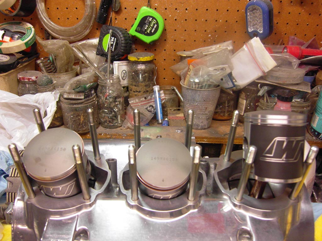
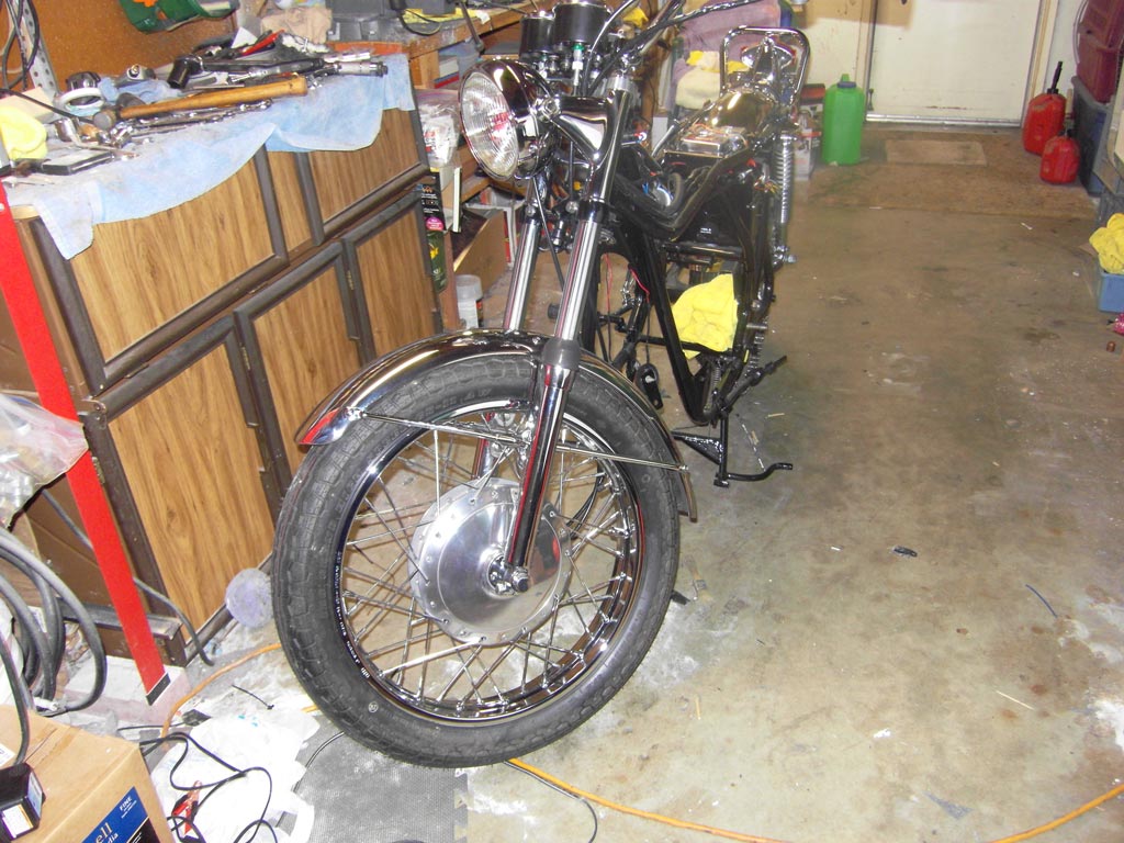
It’s finally starting to look like a motorcycle. I can
see the light at the end of the tunnel and it’s not a freight train.
New clutch friction plates, steel plates, steel rings (Wafer springs), clutch
springs, clutch hub bearing and bushing, gear change lever, distributor
bearings, distributor gear, tachometer gear, distributor rotor, shifter seals,
kick starter seal, 15t sprocket and case screws. Cleaned out all screw and bolt
holes with a wire bottle brush and spray carb cleaner. Installed a used ball
bearing clutch release. Lined up the distributor rotor and installed the clutch
cover. Installed the motor in the frame and shimmed up the engine mount bolts
with fender washers. Installed the re-chromed kick starter with new rubber and a
new re-chromed shifter with new rubber and re-chromed linkage and shifter rubber
cap. Filled up the transmission with Bel-Ray 80w gear oil.
Notes:
Clutch Friction Plates: Bought some EBC clutch friction plates and soaked them
in gear oil for about four hours and installed them and the tabs hit the
distributor pinion gear. The tabs on the EBC plates are a little bit taller than
the ones on the stock plates so I ground them down a bit then deburred and
scrubbed them clean and re-soaked them in oil.
Clutch Springs: Bought some EBC clutch springs but they don’t fit right; the
spring diameter is a little smaller. The spring tower on the hub flairs out at
the bottom and the springs goes on about 3 quarters of the way down before they
get wedged on the spring towers. I bought some Barnett springs and they fit
right.
Gear Change Lever: Upgraded to a new welded gear change lever as the original
one was staked and had a lot of slop in it.
She’s alive, she’s alive, my fire breathing asphalt
eating wheelie machine is finally on the road.
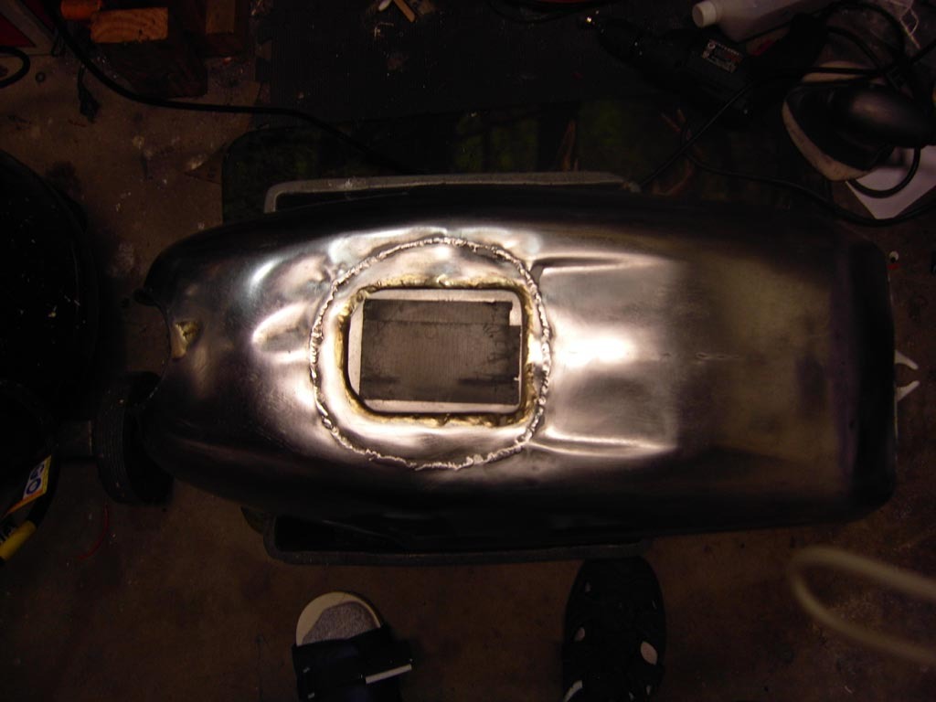
The original owner converted the screw on gas cap to a flip up cap and after
removing the bondo it looks like they ran a continuous weld bead and it
distorted the tank real bad but after about a month I got it looking pretty
good.
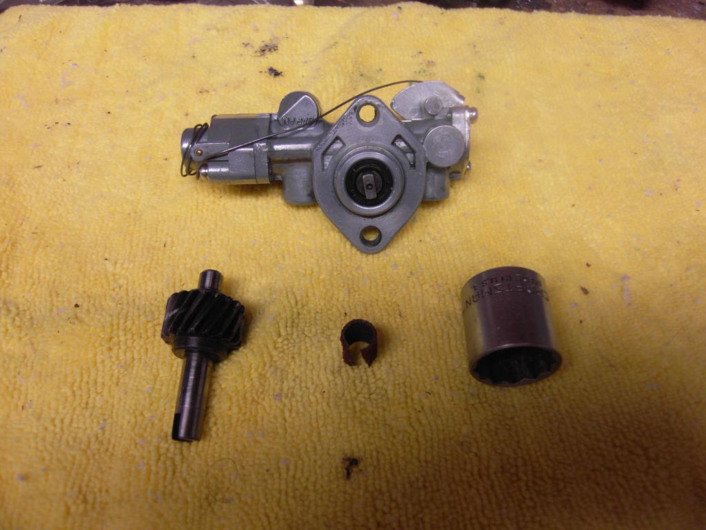
Polished the crankcase covers and installed new case screws and installed the
oil pump and lines.
Rebuilt the carburetors with sudco kits and installed 35 pilot jets and 110 main
jets and set the needle clip to the 3rd grove. New carburetor rubber top caps
and starter caps. Installed new large K&N air filters.
Installed tinned plated copper core silicone spark plug wires with NGK caps and
NGK iridium spark plugs and installed a set of Higgspeed expansion chambers.
New side cover emblem, side cover protectors, reproduction knob with rubber
grommet. New oil tank pipe with gaskets and oil level pipe with gauge and clamps
and a new reproduction seat
I painted the battery box cover with Chrysler stone white and sanded it and shot
just the inside with clear coat to compare clear and non-clear and I like the
non-clear better, looks more vintage. I used royal blue on the tank and no clear
coat; I will have to be careful when refueling not to get any gas on the tank.
Notes:
I put the white side cover emblem (1969) on and I didn’t like the look of white
on white so I got a black side cover emblem (1970) it may not be correct but it
looks a lot better in my opinion.
She is running very rich on low throttle, has kind of a sputtering sound so I
will go back to the 30 pilot jets. Mid throttle sounds good but wide open there
is a very slight hesitation, it’s not stumbling just a very slight delay so I
will go down to a 107.5 main jets and see what happens. I installed the 30 pilot
jets and 107.5 main jets and she runs a lot better.
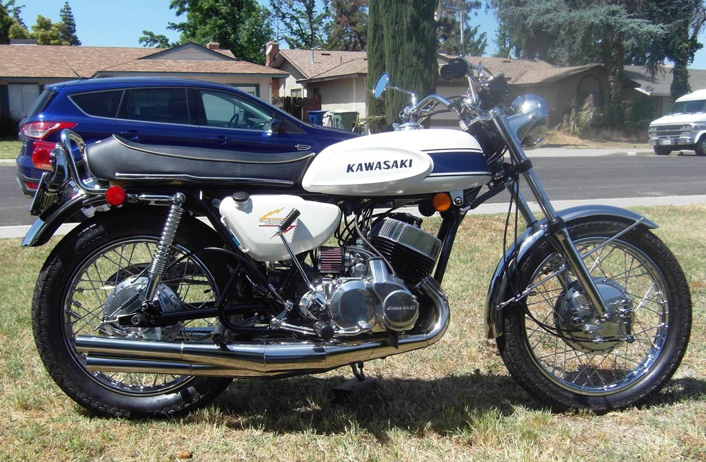
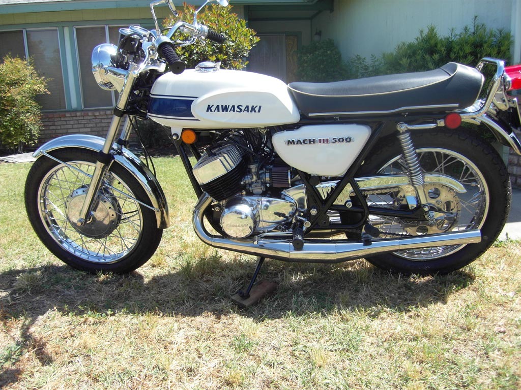
The pictures did not come out to good but here are some before and after
pictures. I will take some more pictures later once I figure out how to use this
camera as these pictures do the bike no justices.
Still need to do a little more sorting and re torque
the heads and check all the nuts and bolts and as Jeff said I need to recheck
the carbs to make sure they are still sync'ed. I plan on changing the gear oil
in about 100 miles.
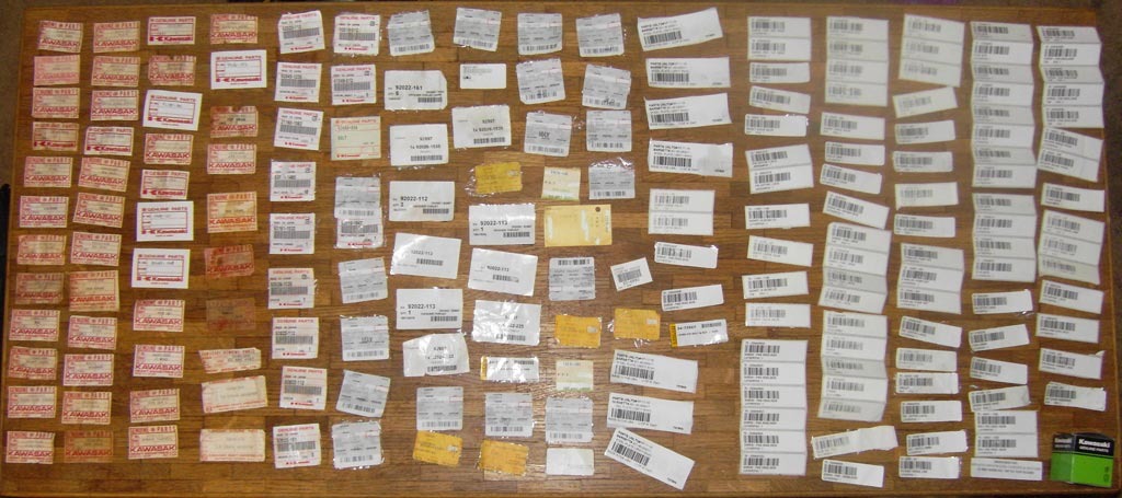
I need to post a picture of something so here are most of the parts tags.