Triple Maintenance Manual
Section 2 - Tuning for Performance
Chapter 2
TUNING FOR PERFORMANCE
To obtain the designed level of performance. the engine must develop maximum
power and efficiency. Careful tuning assures peak engine performance and
reliability. Three elements of the engine affect its state of tune: compression,
ignition, and carburetion.
COMPRESSION
The amount of force delivered to the piston and crankshaft depends on how much
the air/fuel mixture is squeezed before ignition and how well the burning gases
are contained after ignition. In a two-stroke-cycle engine, there are no valves
to leak compression. However, cylinder head sealing, piston ring condition,
cylinder bore finish, and piston clearance all play major roles in combustion
chamber sealing.
To check the compression, warm the engine to normal temperature, then remove the
spark plugs. Use a gauge which registers 200 psi and insert the tip into a spark
plug hole. Twist the throttle to the wide-open position, then crank the engine
with the kickstarter until the gauge levels off at a maximum reading. NOTE:
The compression process begins after the piston crown closes off the exhaust
port during the upstroke. Repeat the process on all cylinders.
Note: Use of a compression gauge with an adapter or extension
can result in inaccurate, low readings.
A good reading, on all H models is 142 psi. The S1/KH250's
should develop 170 psi; S2's, 156 psi; the S3/KH400's, 155 psi. (Note:
altitude correction factor may be required). Excessively high compression
readings are caused by carbon buildup on the cylinder head and piston crown, or
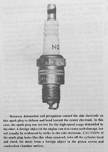
by using no head gasket. Too much compression causes detonation and preignition,
with soaring combustion pressures and temperatures, which result in short spark
plug life.
If the compression reading is less than 70 percent of specifications, or if
there is more than 14 psi difference between any two cylinders, a leak exists
past the piston rings or head gasket. A cracked or warped cylinder head will
also permit compression leakage. An extremely low reading, less than 40 psi,
indicates a piston with a hole burned through the crown or the edge of the
piston crown eroded by detonation.
To check for the source of leakage, squirt a little oil into the spark plug
hole, then turn the crankshaft slowly to coat the piston rings. Crank the engine
and recheck the compression. If it increases with the oil, the piston rings are
worn or stuck in their grooves. If the compression remains low, there is more
than one head gasket installed or the piston is badly damaged.
A cracked cylinder head will have hairline traces of oil on its outer surface.
NOTE: A cracked head or leaking head gasket is sometimes evidenced by a
chirping sound when the engine is running. To pinpoint the leakage at the
cylinder head joint, remove the head and look for oil stains on the top of the
cylinder. A defective cylinder head gasket will be "blown out" or distorted.
NOTE: On S2's before engine number 07595, the cylinder heads were thinner and
prone to cracking near the inner stud bosses. If your engine number is 07595 or
lower and you have a cracked cylinder head, you may have the thinner heads.
Measure from the cylinder head mating surface to the bottom of the fin cutaway.
The old cylinder heads measure 16mm, and the new, thicker heads, 19mm. The two
types can be mixed on one engine without problems.
To inspect a cylinder with low compression, lift the cylinder off the engine
after loosening the exhaust pipe flange. Inspect the upper part of the cylinder
bore for scoring and check the piston for scuffing. Make sure that the piston
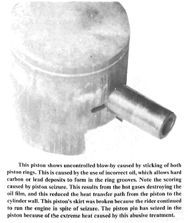
rings are free in their grooves. Stuck piston rings are often the result of
using an improper oil, a detective crankcase seal that permits transmission oil
to be sucked into the engine, an improper oil pump lever ad adjustment or a
defective oil pump. Excessively rich fuel mixtures can promote carbon deposits
in the ring grooves, which will cause the rings to stick. If a ring is tight in
only one section of the groove, look for a deformed ring land caused by
detonation.
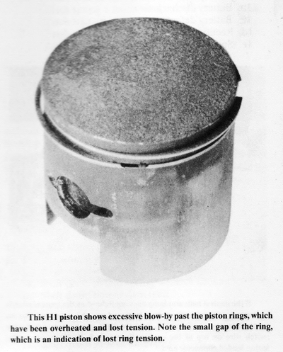
You can estimate how long the rings have been stuck by the amount of blow-by on
the piston skirt, evidenced by the brown coloring below the ring grooves. Slight
blow-by is normal, but with stuck rings and increased blow-by, the hot gases
leak into the crankcase chamber where they change some of the fresh mixture into
carbon particles. The combination of increased crankcase temperature and
abrasive particles results in premature wear of the crankshaft main bearings,
connecting rod bearings, and crankcase seals. Stuck piston rings invite piston
failure for two reasons; (1) The hot gases escape past the rings and destroy the
oil film between the cylinder wall and the piston skirt; (2) Well-seated piston
rings form a thermal link between the hot piston crown and the cooling cylinder
walls. When the rings stick, this heat-transfer path is interrupted, and the
piston runs excessively hot.
IGNITION SYSTEM SERVICE
Servicing the ignition system consists of cleaning and gapping the spark plugs,
cleaning and adjusting the contact points or setting the air gap, and adjusting
the ignition timing. NOTE: Always service the ignition system first before
making carburetor adjustments.
CLEANING AND GAPPING THE SPARK PLUGS
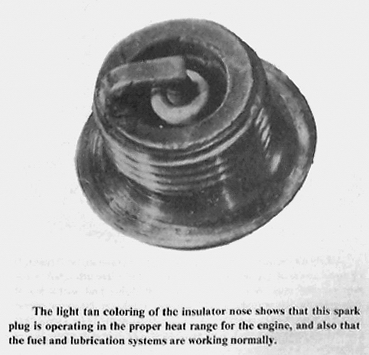
Every 2,000 miles, remove the spark plugs. Inspect the spark plug insulators and
electrodes for signs of unusual deposits, which would indicate malfunctions of
the fuel, ignition, or lubrication systems. If the spark plug heat range is
correct, and the engine systems are working properly, the spark plug insulator
nose will be colored light brown to light tan.
In normal use, the firing end of the center electrode is rounded off from
erosion and heat. The increased resistance requires more voltage to fire the
plug gap, and this demands more output from the ignition system. Misfiring and
hard starting occur when the spark plug's required voltage exceeds the
capability of the ignition system. To reduce the plug's firing voltage, it is
necessary to file the corroded surfaces of the electrodes, clean the insulator,
and then adjust the electrode gap to the specified clearance.
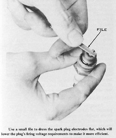
To clean the electrodes, bend up the side electrode slightly, and then use a
point file to dress the end of the center electrode until it is flat and has a
square edge. Use the file to clean the side electrode in the same manner. Clean
off any insulator deposits with a long, pointed probe, and then wash out
remaining particles with gasoline. CAUTION: If the spark plug is cleaned in a
sandblasting device, wash the insulator cavity with gasoline, and then blow it
out with compressed air to remove the abrasives; otherwise you can cause ring
and cylinder damage from continuing abrasive action from contaminated oil.
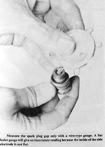
Measure the spark plug gap with a wire-type gauge and compare with
specifications. CAUTION: Make sure the bending tool doesn't contact the
insulator or you will crack it. Bend or tap the side electrode to obtain the
proper gap.
If the spark plug electrodes are worn or the insulator is
damaged, install a new spark plug. CAUTION: Be certain the replacement spark
plug is one with the specified reach and heat range. NOTE: If an S1 or S2
model is driven continually on the highway, a one-step colder heat-range spark
plug should be installed to prevent overheating. To overcome misfiring or
fouling troubles often encountered with colder heat-range spark plugs,
particularly under hard acceleration, widen the electrode gap 0.002-0.004" more
than specifications. CAUTION: Never use a hotter-than-standard spark plug in
an attempt to prevent chronic fouling, or else major engine damage can occur
from overheating. Instead, locate the cause of the excessive spark plug
deposits and make the necessary repairs.
Replace the spark plug gaskets if they are deformed or notched. NOTE: The
spark plug transfers about 40 percent of its heat through the gasket seat; a
deformed gasket can interfere with the proper heat transfer from the plug shell
to the cylinder head and cause the plug to run hotter. A notched spark plug
gasket permits the burning gases to escape in a concentrated stream, which can
burn out the spark plug or cylinder head threads.
Thread the spark plug, with a new gasket, into the cylinder head about three
turns, and then use compressed air to blow off any dirt from the spark plug
seat. Finger tighten the spark plug, and then tighten it 1/4 turn more with a
socket. NOTE: With a new gasket, tighten it 1/2 turn. If a torque wrench
is used, tighten the spark plug to 15 ft-lbs. of torque.
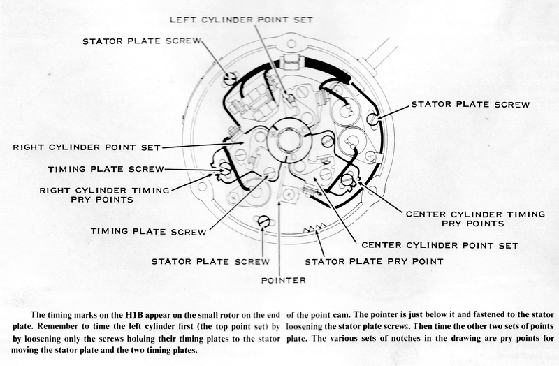
CONTACT POINTS-S-SERIES AND H1B
The surface condition of the contact points affects the voltage delivered to the
spark plug by the high-tension coil. Oily or dirty points restrict the current
passing through them and thus limit the coil's output. During an extended period
of operation, the breaker arm rubbing block wears against the breaker cam, and
the point gap is reduced. The narrow point gap retards ignition timing and also
causes arcing and consequent burning of the point surfaces.
CLEANING AND GAPPING INSTRUCTIONS
Every 2,000 miles, clean and adjust the gap of the contact points, and then
check the ignition timing. Adjust as required. NOTE: Any change in the point
gap affects the ignition timing. CAUTION: Always check the ignition
timing after the contact points have been serviced; otherwise, engine
performance and reliability will suffer.
To gain access to the contact points, remove the left engine cover. Use a wrench
to turn the crankshaft until one set of contact points is closed. Lift the
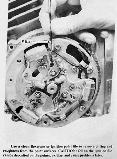
breaker arm and insert a flexstone between the points. Run the flexstone back
and forth to dress off pits and roughness. Clean off all oil and metal
particles with a strip of lintless paper (such as a business card) soaked in
trichloroethylene, and continue drawing new strips through the closed points
until all traces of oil and dirt are removed. Use this procedure for all three
sets of points.
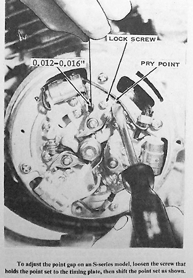
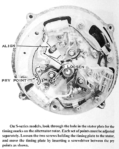
To measure the point gap, turn the crankshaft until one set of points is at its
widest gap, and then set the point gap. NOTE: The point gap should be 0.3 to
0.4mm (0.012" to 0.016"). When properly adjusted, a 0.014" feeler gauge
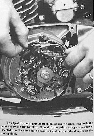
should slide between the points with a slight drag. To adjust the point gaps.
loosen one point plate screw 1/2 turn, and then wedge the screwdriver blade
between the point plate notch and the timing plate dimples. Turn the blade
clockwise to widen the gap or counterclockwise to narrow it. Tighten the point
plate screw and recheck the point gap, which may change after tightening. Repeat
the procedure for the other two sets of points, and then you are ready to check
and adjust the ignition timing.
SIGNAL COIL AIR GAP
The CDI (Capacitor Discharge Ignition) models do not have contact points.
Instead they have one, two, or three signal coils (depending on the model),
which must have the proper air gap between them and the rotor tangs.
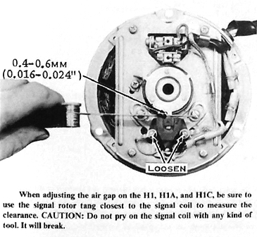
To set the air gap, remove the ignition cover on the left side of the engine,
then turn the crankshaft until one of the tangs in the signal rotor is closest
to a signal coil. Measure the gap and make a note of it. Turn the crankshaft and
measure the gap between the same signal coil and the other signal rotor tangs.
One tang will be closer to the signal coil than the other two. CAUTION: This
tang must be used to set the air gap. If the closest tang is not used to set the
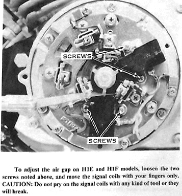
air gap, it can strike the signal coil when the engine is running. Loosen
the two screws holding the signal coil to the stator plate, and then shift it
until the proper gap, as measured with a feeler gauge, exists between the signal
coil and the signal rotor tang. CAUTION: Do not pry on the signal coil with
any kind of tool. It is very delicate and will break easily. Move it only with
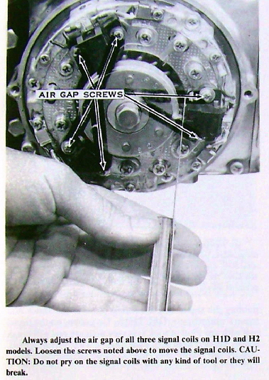
your fingers. The air gap for the H1, H1A, and H1C models is 0.016" to
0.024"; for the H1D, H2, H2A, H2B, and H2C models it is 0.020" to 0.031"; and
for the H1E and H1F models it is 0.020" to 0.030". Set the gap for all the
signal coils the same way. Be sure all the screws are tight, then check the gaps
once more, as they sometimes change when the screws are tightened.
IGNITION TIMING
An engine develops maximum output only when the pressure of the burning,
expanding gases on the piston crown reaches its peak at around 10° ATDC (after
top dead center). The spread of the flame through the compressed mixtures takes
a definite length of time, around 0.0006 second. At high engine speeds, this
corresponds to 30° of crankshaft rotation. Therefore, an initial spark advance
(or static ignition timing) of approximately 20° BTDC (before top dead center)
is required to anticipate the delay between ignition spark and the development
of maximum pressure on the piston.
Since the spark plug fires the instant the contact points open or when the
proper relationship exists between the signal coil and the signal rotor tang,
the ignition timing is checked by comparing the opening of the points (or the
positions of the signal coil and the signal rotor tang) against the crankshaft
angle (timing marks) or against the piston position (measured with a dial
indicator).
The magneto-type CDI installed on the H1D, H1E, H1F, H2, H2A, H2B, and H2C
models incorporates a spark advance resulting from variations in signal coil
voltage and electronic circuitry. This ignition system must be checked
dynamically with a stroboscopic timing light, as well as statically.
CHECKING THE IGNITION TIMING
There are two methods of checking the static ignition timing; matching the
timing marks, or measuring the piston movement from TDC (top dead center) with a
dial indicator. Matching the timing marks is the simplest method, but it may not
be completely accurate, because of production tolerances in stamping the marks
and machining the keyways the crankshaft and rotor. A bent timing pointer (or
shifted stator plate) can also result in incorrect positioning of the stationary
timing mark. Using the dial indicator eliminates these inaccuracies, because the
points are adjusted to open at the exact piston position and therefore at the
specified crankshaft angle. The dial indicator can also be used to verify the
accuracy of the timing marks, after which they can be used with confidence.
MATCHING THE TIMING MARKS-S-SERIES AND H1B
Adjust the ignition timing only after having cleaned the points and adjusted
their gap. Attach a self powered continuity lamp across one set of points by
connecting one lead to any metal part of the engine (ground) and the other lead
to the breaker arm spring. CAUTION: Make sure the main switch is in the OFF
position, or else the lamp will be energized by the motorcycle's battery.
Slowly turn the crankshaft in the normal direction of rotation
(counterclockwise) and watch the continuity lamp, which will go out when the
points open.
If the timing is correct. the points will open just as the timing mark on the
edge of the rotor coincides with the pointer's mark. If the points open before
the marks coincide. the ignition timing is advanced: if they open after the
marks coincide. the timing is retarded.
To adjust the ignition timing, loosen by 1/2 turn the two screws securing the
timing plate. Wedge a screw-driver blade between the tinning plate notch and the
stator plate dimples. If the timing is advanced, turn the screwdriver clockwise
to retard it: if retarded, turn the screwdriver counterclockwise to advance it.
Tighten the timing plate screws, recheck the point gap, and then recheck the
ignition timing. Repeat the procedure for the other two sets of points.
Burnish the closed point surfaces by drawing strips of lintless paper through
them until no trace of dirt or oil is left, and then install the left engine
cover.
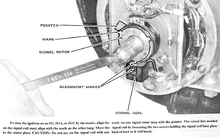
MATCHING THE TIMING MARKS-H1, H1A, H1C
Adjust the ignition timing only after having set the air gap. Turn the
crankshaft until the mark on one of the signal rotor tangs aligns with the
pointer on the stator plate (located at about 10 o'clock). One signal rotor tang
will point straight toward the signal coil. The mark on that tang should align
with the raised line molded on top of the signal coil. If it does not. loosen
the two screws holding the signal coil mounting plate to the stator and move it
accordingly. CAUTION: Do not pry on the signal coil with any kind of tool. It
is very delicate and will break easily. Move it only with your fingers.
Tighten the screws, recheck the timing, and then replace the ignition cover.
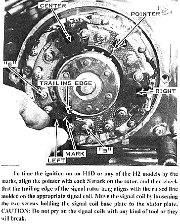
MATCHING THE TIMING MARKS-HID, H2, H2A, H2B, H2C
Adjust the ignition timing only after having set the air gap. Turn the
crankshaft until the S mark on the
signal rotor nearest the L mark aligns with the pointer on the stator (located
at about 2 o'clock). The trailing edge of the rotor tang should align with the
raised line molded onto the top of the left cylinder signal coil (located at
about 7 o'clock). If it does not align, loosen the two screws holding the signal
coil mounting plate to the stator, and then move the signal coil as required.
CAUTION: Do not pry on the signal coil with any kind of tool. It is very
delicate and will break easily. Move it only with your fingers. When the
marks align, tighten the screws and recheck the alignment. Now, rotate the crank
till the S mark nearest the R mark aligns with the pointer and repeat the
procedure for the signal coil at 4 o'clock. Rotate the crank again to align the
S mark nearest the C mark with the pointer, and then repeat the procedure for
the top signal coil.
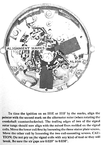
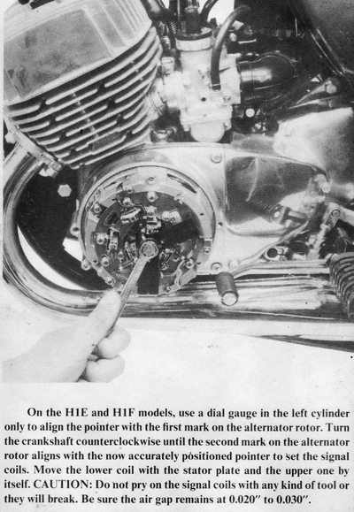
MATCHING THE TIMING MARKS-H1E, H1F
Adjust the ignition timing only after having set the air gap. Turn the
crankshaft counterclockwise until the second notch on the edge of the alternator
rotor aligns with the pointer (located at 10 o'clock). The trailing edges of two
of the signal rotor tangs should align with the raised lines molded onto the
tops of the signal coils. If the lower signal coil does not align. loosen the
three base plate screws, then rotate the entire base plate as required. Tighten
the base plate screws securely, and then recheck the alignment. If the upper
signal coil does not align, loosen the signal coil mounting screws and then move
the signal coil as required. CAUTION: Do not pry on the signal coil with any
kind of tool. It is very delicate and will break easily. Move it only with your
fingers. Tighten the screws, and then recheck the alignment and the air
gaps.
CHECKING THE IGNITION TIMING WITH A DIAL GAUGE
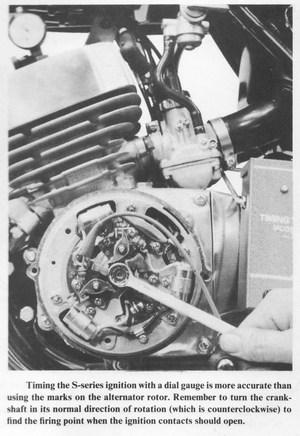
S-series Models
Remove all spark plugs, and then screw a dial gauge adaptor into the left-hand
spark plug hole. leaving the clamp screw loose. Turn the crankshaft with a
wrench until TDC is indicated by the needle's reversing direction. Push the dial
gauge into the adaptor until the small pointer registers 5mm. CAUTION: If the
dial gauge is forced past 5mm, the delicate internal mechanism will be jammed.
Tighten the adaptor clamp screw to secure the dial gauge in this position. Turn
the crankshaft back and forth past TDC while rotating the dial bezel so that the
needle registers zero just as it reverses.
Starting with the crankshaft and piston at TDC (needle at zero), slowly rotate
the crankshaft clockwise. Count the number of rotations of the needle, and then
stop when the needle indicates a piston drop of 2.60mm. This is exactly 23°
before TDC. The mark on the stator plate near the window (located at 10 o'clock)
should align with the mark near the L on the face of the alternator rotor. If it
does not, make a small scratch mark on the stator plate that does align. Move
the dial gauge to the other two cylinders and repeat the procedure. The ignition
should now be timed (using the corrected timing marks) as described in the
previous section.
Alternatively, you can use the self powered continuity lamp with the dial gauge
instead of marking the stator. When the engine is rotated counterclockwise, the
continuity lamp should light just as the dial gauge indicates 2.60mm. Turn the
crankshaft counterclockwise to about 2.70mm, and then turn it slowly clockwise;
the light must go out as the needle registers 2.60mm. Be sure to move the dial
gauge to the other two cylinders to be sure all three are timed properly.
After timing all three sets of points, replace the spark plugs, the spark plug
wires, and the ignition cover. Be sure to put the right wires on the right spark
plugs.
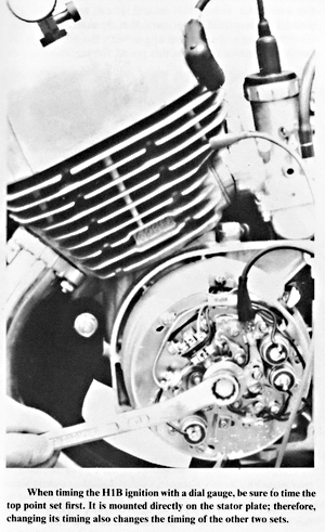
H1B Models
The procedure for timing the H1B with a dial gauge is very similar to the
S-series procedure described above. Remove all three spark plugs, and then screw
the dial gauge adaptor into the left-hand spark plug hole. CAUTION: Do not
tighten the clamp. Turn the crankshaft with a wrench until the needle's
reversing direction signals TDC. Push the dial gauge into the adaptor until the
small pointer registers 5mm. CAUTION: If the dial gauge is forced past 5mm,
the delicate internal mechanism will be damaged. Tighten the clamp screw to
secure the dial gauge in this position. Turn the crankshaft back and forth past
TDC while rotating the bezel on the dial gauge so that the needle registers zero
just as it reverses.
Connect one lead of a self powered continuity lamp to the arm of the movable
point and the other to a good ground, such as a cylinder fin. CAUTION:
Be sure the switch is turned OFF or the motorcycle's battery with light the
lamp.
Starting at TDC, slowly rotate the crankshaft clockwise. Count the number of
rotations of the needle and stop when the needle indicates a piston drop of
2.94mm. This is exactly 23° before TDC. The lamp should light. Turn the crank
past this point to about 3.10mm. Now turn it counterclockwise until the dial
gauge indicates 2.94mm. The light should go out at exactly at this point.
If it does not, loosen the three stator plate screws and move the entire stator
plate until the light goes out at exactly 2.94mm. Tighten the stator plate
screws securely, then check the timing again. Now move the dial gauge to the
other two cylinders and repeat the procedure with the following single
difference. When setting the timing of the center and right-hand cylinders,
do not loosen the for plate screws; loosen only the two screws that hold
that one set of points. After timing all three sets of points, check that the
point gaps are still between 0.012" and 0.016". Replace the spark plugs, spark
plug wires, and ignition cover. Be sure to put the right wires on the correct
spark plugs.
H1, H1A, H1C Models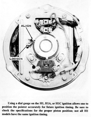
Remove all three spark plugs and the ignition cover on the left side of the
engine. Screw a dial gauge adaptor into the left cylinder spark plug hole,
leaving the clamp loose. Turn the crankshaft with a wrench until TDC is
indicated by the needle's changing direction. Push the dial gauge into the
adaptor until the small pointer registers 5mm. CAUTION: If the dial gauge is
forced past 5mm, the delicate internal mechanism will be damaged. Tighten
the adaptor clamp screw to hold the dial gauge in this position. Turn the
crankshaft back and forth past TDC while turning the dial bezel so that the
needle registers zero just as it reverses.
Starting with the crankshaft at TDC, slowly rotate it clockwise. Count the
number of rotations of the needle, and stop when the needle indicates 3.45mm.
This is exactly 25° before TDC. The raised line molded into the top of the
signal coil should align with the mark on the signal rotor tang. If it does not,
loosen the three screws that hold the signal coil base plate to the stator plate
and move the signal coil as required. CAUTION: Do not pry on the signal coil
with any kind of tool. It is very delicate and will break easily. Move it only
with your fingers. Tighten the signal coil base plate mounting screws, and
then check the air gap, which must be from 0.016" to 0.024". Now loosen the
screw that holds the pointer (located at about 10 o'clock) to the stator plate.
Move the pointer so it aligns with the mark on the closest signal rotor tang,
then retighten the screw. The ignition can be timed from now on (without the use
of the dial gauge) by just matching the pointer with the mark as described in
the previous section.
Replace the spark plugs, spark plug wires, and ignition cover. Be sure to put
the right spark plug wires on the correct plugs.
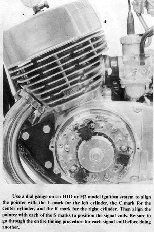
HID, H2, H2A, H2B, H2C Models
Remove all spark plugs, and then screw a dial gauge adaptor into the left spark
plug hole, leaving the clamp screw loose. Turn the crankshaft back and forth
until TDC is indicated by the needle's reversing direction. Push the dial gauge
into the adaptor until the small pointer indicates 5mm. CAUTION: If the dial
gauge is forced past 5mm, the delicate internal mechanism will be jammed.
Tighten the clamp screw to secure the dial gauge in this position. Turn the
crankshaft back and forth past TDC while rotating the dial bezel so that the
needle registers zero just as it reverses.
Starting with the crankshaft at TDC. slowly turn it clockwise. Count the number
of rotations of the needle and stop when it indicates a piston drop of 3.45mm
(25° BTDC) for the H1D and 3.13 mm (23° BTDC) for the H2 models. Now the pointer
on the stator plate (located at about 2 o'clock) should align with the L mark on
the edge of the signal rotor. If it does not, bend it carefully as required. Now
turn the crankshaft so that the pointer aligns with the S mark nearest the L
mark. The trailing edge of the signal rotor tang should now align with the
raised line molded onto the signal coil. If it does not, loosen the two signal
coil base plate mounting screws and move the signal coil as required.
CAUTION: Do not pry on the signal coil with any kind of tool. It is very
delicate and will break easily. Move it only with your fingers. Move the
dial gauge to the other two cylinders, and then repeat the procedure with the
other two signal coils. When the ignition is timed properly, the air gap must be
between 0.020" and 0.031". Replace the spark plugs, spark plug wires, and
ignition cover. Be sure to put the right wire on each of the spark plugs.
H1E and H1F Models
Remove all spark plugs and then screw a dial gauge adaptor into the left
cylinder spark plug hole, leaving the clamp screw loose. Turn the crankshaft
with a wrench until TDC is indicated by the needle's reversing direction. Push
the dial gauge into the adaptor until the small pointer registers 5mm.
CAUTION: If the dial gauge is forced past 5mm, the delicate internal mechanism
will be jammed. Tighten the clamp screw to hold the dial gauge in this
position. Turn the crankshaft back and forth past TDC while turning the dial
bezel so that the needle registers zero just as it reverses.
Starting with the crankshaft at TDC, slowly rotate it clockwise until the dial
gauge indicates a piston drop of 2.94mm, which is exactly 23° BTDC. If the
pointer (located at 10 o'clock) does not align with the mark on the alternator
rotor, loosen the screw and move the pointer as required. Now turn the
crankshaft counterclockwise until the pointer aligns with the second mark on the
alternator rotor. At this point, the trailing edge of one signal rotor tang
should align with the raised line molded onto the signal coil located at 6
o'clock. If it does not. loosen the three stator plate screws and move the
entire stator plate as required. After tightening the screws, check that the
trailing edge of the right signal rotor tang aligns with the mark on the other
signal coil. If it does not, loosen the two signal coil mounting screws and move
it as required. CAUTION: Do not pry on the signal coil with any kind of tool.
It is very delicate and will break easily. Move it only with your fingers.
Tighten the screws carefully, then check the air gap. which must be 0.020" to
0.030". Replace the spark plugs. spark plug wires, and the ignition cover. Be
sure to put the wires on the right spark plugs.
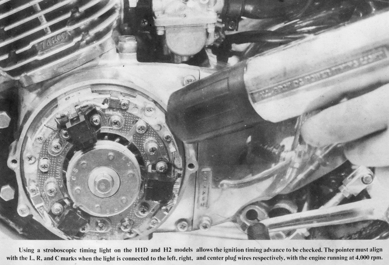
IGNITION TIMING WITH A STROBOSCOPIC TIMING LIGHT
This procedure is required only on the magneto-powered CDI models (H1D. H1E.
H1F, H2. H2A, H2B, and H2C). Warm the engine to normal operating temperature.
Shut it off, remove the ignition cover, and attach a stroboscopic timing light
to the left cylinder spark plug wire.
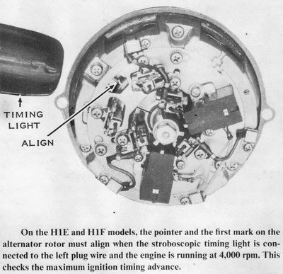
Start the engine and have a helper hold it at 4,000 rpm. The pointer should
align with the notch on the alternator rotor on the H1E and H1F models and with
the L mark on the H1D and H2 models. If it does not, loosen the stator plate
screws on the H1E and H1F or the lower left signal coil base plate mounting
screws on the other models. and change the ignition timing as required. The
other two cylinders on the H1E and H1F are now timed properly. On the H1D and H2
models, however. the center and right cylinders must be timed separately. Move
the timing light leads to each of the other two spark plug wires and check the
timing again. The top signal coil times the center cylinder; the right-hand
signal coil times the right cylinder. When the timing is properly set, remove
the timing light, check that all screws are secure, and replace the ignition
cover.
FUEL SYSTEM TUNING NOTES
Carburetor adjustments are affected by compression and ignition conditions;
therefore, carburetor tuning must be done only after all other adjustments have
been made. Periodic carburetor tuning consists of checking the adjustment of the
cold-start cables, adjustment and synchronization of the throttle cables and oil
pump cable, and then adjusting the idle mixture and idle speed screws.
The cold-start cables must be adjusted to make sure that the cold-start devices
work properly during cold engine starting but do not interfere with normal
engine operation when shut off. The throttle cables must be set so that the
carburetor throttle valves open all the way to obtain maximum engine
performance. After the throttle cables are checked, the oil pump cable must be
adjusted to "time" the oil pump control lever (which varies oil flow to the
engine) with the throttle valves. After the initial adjustment, these cables
generally require inspection (not adjustment) only at 2,000-mile intervals,
because cable stretch is negligible.
After the ignition timing is reset, the engine's idling characteristics may
change. This condition requires adjustments to the idle speed and idle mixture
screws to obtain a satisfactory idle. The other specified carburetor settings,
such as jet needle clip position, main jet size, idle jet size, and float level
should not be changed for most types of riding. If, however, the motorcycle is
ridden at high altitudes or constantly at high speeds, refer to Chapter 3, Fuel
System Service, for instructions on making these tuning adjustments to the
carburetor.
ADJUSTING THE COLD-START CABLES
Check the cold-start cable slack by tugging on the cable sheath at the
cold-start lever. There must be 1/16" to 1/8" slack in the cable with the lever
released. If there is no slack in the cable, the cold-start plunger may be held
off its seat, causing rich fuel mixtures and increased exhaust emissions,
especially at low throttle openings. If the cable slack is excessive, the
cold-start system will not work properly, causing difficult starting with a cold
engine.
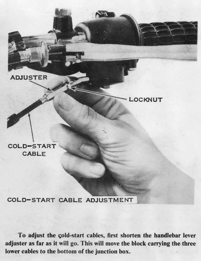
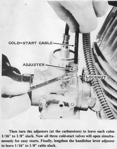
To adjust the cold-start cables, loosen the adjuster locknut at
the handlebar lever, and then shorten the adjuster till the cable sheath has at
least 1/4" free play. Pull up the rubber boots from the carburetors and loosen
the adjuster locknuts. Turn out the cable adjuster if cable slack is excessive;
turn it in if there is no slack. Tighten the locknuts and replace the rubber
boots. Now lengthen the adjuster at the handlebar lever until the cable sheath
has 1/16" to 1/8" free play. Tighten the locknut.
ADJUSTING THE OIL PUMP LEVER
If the oil pump lever is short of its specified position, insufficient oil flow
can cause engine overheating and piston seizure. If the oil pump lever is pulled
past the specified position, excessive oil flow will cause spark plug fouling,
rough engine operation, excessive exhaust smoke, and increased exhaust
emissions.
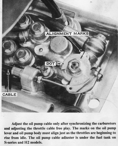
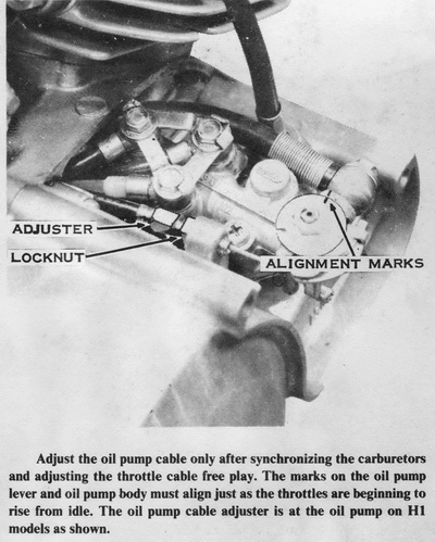
To adjust the oil pump lever, remove the oil pump cover on the
right side of the engine. The mark on the lever should align with the mark on
the boss on the oil pump body when the throttle is just beginning to open. If it
does not, loosen the cable adjuster locknut. NOTE: The adjuster is located on
the cable sheath anchor near the oil pump on H1 models, and on the cable under
the fuel tank on all other models. Turn the adjuster as required to align
the marks, and then tighten the locknut. NOTE: If this setting results in
excessive exhaust smoke on H1, H1A, H1B, and H1C models (1969-1972), readjust
the pump lever at full throttle so that the second dot on the lever aligns with
the mark on the pump body. Replace the oil pump cover.
OIL PUMP SERVICE NOTES
The oil pump lever may not return to its normal idle position when the engine is
shut off because the lever camshaft is rubbing against the plunger nose inside
the pump. This does not indicate a defective pump. When the engine is running,
however, the oil pump lever must return completely to the idle position when the
throttle is opened and then released. If the lever does not return under these
conditions, check the oil pump cable for binding and make sure that the return
spring is correctly installed on the lever. A sticking oil pump lever supplies
too much oil to the engine for part-throttle operation, which can cause spark
plug fouling and rough engine operation.
The control lever on a new oil pump may not return because of tight, dry, lever
shaft seals. To correct this problem, install a temporary auxiliary coil spring
on the oil pump cable between the lever and the cable adjuster. The spring can
be removed after the seal loosens sufficiently to permit free lever movement .
Spray the shaft with silicone lubricant to speed up the wearing-in process.
CAUTION: If lubrication system oil leaks from the lever shaft hole in the pump
body, replace the pump, because such leakage is evidence of reduced oil output
to the engine, which can result in its destruction.
SYNCHRONIZING THE CARBURETORS
In order for the engine to run smoothly and deliver the best performance and
fuel mileage, all three carburetors must act together. They must be synchronized
so that all three throttles lift the same amount at the same time and so that
all three pilot systems and main systems are working in unison. It is important
to understand that synchronizing carburetors means that the slides are all
positioned equally in height within the carb bore at ALL throttle positions as
well as idle position.
To synchronize the carburetors, first warm the engine to operating temperature,
then switch it off. Loosen the throttle cable adjuster at the twistgrip to get
as much cable slack as possible. This moves the sliding block that carries the
four lower cables (one to each carburetor and one to the oil pump) all the way
to the bottom of the cable junction box. Shorten the cable adjusters on the
carburetor caps all the way. Remove any cable clips from the adjusters.
Now remove the air pipes from the mouths of the carburetors. Set all three air
screws to the setting recommended in the specification section at the end of
Chapter 3, Fuel System Service. Lower all three throttle slides as far as they
will go by turning the throttle stop screw or adjuster. On H2's, S2's, and S3's,
turn the throttle stop screw counterclockwise. On H1's and S1's turn the
throttle stop adjuster clockwise. Feel with your fingers or use a mirror to see
that all three throttle slides are at the bottom of their travel. Turn each
throttle stop in the opposite direction until each slide just begins to
lift, and then turn it one additional turn. This will synchronize all three
carburetors at a slow idle.
Start the engine. If it will not run, turn each throttle stop exactly one more
turn to speed up the idle slightly. To increase engine idling speed to
specifications, turn all three throttle stops 1/4 turn at a time in the same
direction, until the idle is constant at 1,100 to 1,300 rpm.
If you have access to a Uni-Syn or similar air speed sensing tool, hold it
against the mouth of each carburetor in turn and adjust the throttle stops until
the ball is lifted the same height on each carburetor. Then turn all three
throttle stops 1/4 turn at a time in the same direction until the idle is
constant at 1,100 to 1,300 rpm. Switch off the engine.
Lengthen each cable adjuster on the carburetor cap until the cable sheath has
1/16" free play. Now turn the cable adjuster at the twistgrip until the grip
also has 1/16" free play. While turning the twistgrip back and forth, check with
your fingers or a small mirror to be sure that all three throttle slides start
to lift at exactly the same time. Replace the air pipes and any dust covers and
cable clips that were removed.
There are a couple of alternative carburetor synchronization methods offered below that may offer greater precision:
ALTERNATIVE SYNCHRONIZATION METHOD 1:
1) First back off the idle screws until they don't touch the slides.
2) Carefully screw each one in until the screw just barely touches the slide.
3) Turn in each screw the exact same amount, until you get your target idle number. If you don't do this first, the little variance you get when setting the idle screws will affect slide height and the sync will not be "spot on".
4) Make sure you have slack in the cables.
5) Put your middle finger of your left hand on the center slide, and your thumb (left hand) on the right slide. Turn the throttle very slowly and feel if the slides lift at the same time. If not, adjust one or the other cable so they do.
6) Snap the throttle a couple of times to make sure the slides are setting in well, and tighten the cable lock nut and recheck.
7) Move your thumb to the center slide and your middle finger to the left carb. Adjust the LEFT carb till it lifts exactly with the center.
8) Snap the throttle again and make sure the lock nut is tight (tightening the lock nut will change the slide height).
9) Open throttle until slide is even with top of carb throat. Feel that all slides are at the same position.
10) Take out any extra slack in the cable, AND check the oil pump for correct setting.
The finger method can tell movement in thousands of an inch (just say very accurate). Set the sync from idle, because that is where it is most important.
ALTERNATIVE SYNCHRONIZATION METHOD 2:
1) Find a smooth round pin about 3/8" or 10mm dia. (the shank of drill bit works well).
2) Remove air box/filters.
3) Back out slide stop (idle adjustment) screws.
4) Set throttle lock or set throttle adjuster at the grip so the pin will just lightly drag as it is inserted in the carb throat under the slide cutaway of one carb.
5) Set the other carbs so they offer the same resistance when the pin is inserted by setting the cable adjuster at top of each carb.
6) Release throttle lock or reset throttle adjuster at grip insuring that slides on all carbs will fully bottom out and throttle grip has 2-3mm play.
7) Set idle adjustment screw for best idle on any carb.
8) Set idle adjustment screw on remaining carbs until further rotation increases RPM.
9) Recheck oil pump position setting.
As a final check to insure all idle adjustment screws are set the same, insert a nail, spoon, or long toothpick under each slide without altering slide position. As the grip is turned the ends of all three should tip at the same time. Readjust idle screws as required.
ADJUSTING THE THROTTLE DRAG
All Models
The 1974 and earlier throttle control has a friction drag adjusting screw
(located just below the twistgrip housing), which determines how freely the
twistgrip turns. Normally, the screw is set for minimum drag so that the
twistgrip returns to idle when released. For long-distance riding at constant
speeds, however, the drag screw can be adjusted to hold the throttle in any
position, relieving tension from the rider's hand.
To adjust the throttle drag, loosen the locknut on the drag screw and turn it in
to increase friction drag on the twistgrip. CAUTION: Don't tighten it too
much or it can prevent the throttle from closing at all. To remove all drag,
back out the screw until resistance is felt.