Triple Maintenance Manual
Section 3 - Fuel System Service
The fuel system is composed of the fuel tank and cap, fuel cock or valve, fuel lines, and carburators. The carburetor air cleaner and its ducting will also be covered here.
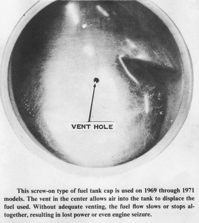
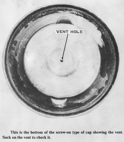
The Kawasaki triples have had four different fuel tank caps. One is a twist-on type with a rubber gasket, which appeared on the H1 and H1A. It has a vent hole in the center of the inside and outside walls. There is a baffle in between to prevent fuel loss on acceleration and braking. If the vent clogs, the fuel will not be able to flow to the carburetors. To check the vent, blow through it from the outside.
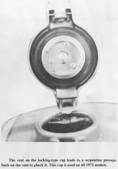
The second type of cap is found on all the 1972 models: H1B, H1C, S2, and H2. This cap is hinged to the tank at its front edge. To open, push the cap down, pull the latch up, and release the cap. The vent is a small hole on the bottom side of the cap outside the rubber gasket by way of a serpentine passage. Again, to check the vent, blow through the hole.
The third type of cap is similar to the second except it has a locking feature. To open, unlock the button, hold the cap down, push the button, then release the cap. This type is used on three 1973 models: the S1A, S2A, and the H2A.
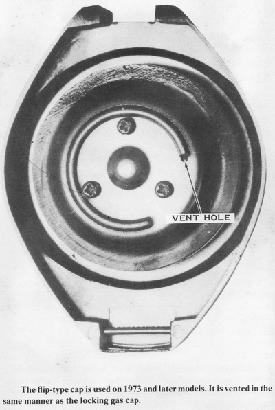
The fourth type of cap is used on the 1973 H1D model, on the 1974 S1B, S3, H1E, and H2B models, and on the 1975 S1C, S3A, H1F, and H2C models. This type of cap is hinged at the rear. To open it, hold the cap down, push the latch down, and release the cap.
To clear a clogged fuel tank cap vent on any of the four types, blow it out with compressed air. The twist-on type of cap is riveted together and cannot be disassembled. The other three types are easily disassembled for cleaning by removing the three screws on the bottom of the cap. If the cap leaks fuel when the tank is full, check the rubber gasket for cracks or tears. To replace the gasket, just pull it over the center section of the cap.
To replace any of the hinged caps or their latches, drive the pin out of the hinge with a 1/16-inch pin punch and a small hammer. Be very careful not to hit the fuel tank with the hammer. Hold onto the cap or latch as the pin punch is withdrawn because the cap and latch are spring loaded. Do not lose the spring. Start the pin into the tab on the tank before compressing the spring and cap (or latch) into place. When it is positioned properly, drive the pin in.
REMOVING
Models H1, H1A, H1B, H1C
Lift the seat and remove the single bolt at the rear of the tank. Remove the
two bolts on either side of the tank at the front. These bolts also hold on the
yellow side reflectors. Turn the fuel cock to the ON or RESERVE position and
then pull off all four tubes. NOTE: Fuel will not run from the fuel cock unless
it is in the PRIME position. Lift the rear of the tank until the fuel cock
clears the frame, then pull the tank straight back.
All Other Models
All other Kawasaki triples have an elastic strap or a "snap-in" type of rubber
fitting instead of a bolt at the rear of the tank. The front is held in place by
two rubber dampers, one on each side of the frame. The tank has channels that
fit over the dampers. To remove this type of tank, lift the seat and remove the
strap (if there is one). Turn the fuel cock to OFF in the case of S-series
models, or to ON or RESERVE for all others, and then pull off the fuel hoses
(three on S-series, four on all others). Lift the rear of the tank until the
fuel cock clears the frame, and then pull the tank straight back.
Use a large open-end wrench (27mm for S-series, 30mm for H-series) to loosen the
fuel cock ring nut. CAUTION: Be prepared to drain the fuel into a container.
CLEANING AND INSPECTING
Check all welded seams of the fuel tank for cracks and signs of leakage,
especially around the mounting brackets and fuel valve threaded fitting. Leakage
around the filler neck on a twist-on type of tank is usually caused by a
deformed flange. To inspect for warping, place a flat surface on the neck flange
and look for a gap that would allow leakage.
Drain the fuel tank into a container. Look for paint chips, rust, dirt, or
water. Look inside the tank for signs of rust. To clean a rusty fuel tank, pour
in kerosene or commercial rust-removing solution and add a number of large bolts
and nuts. Shake the tank vigorously while changing its position to scour all the
inside surfaces. Empty the tank and flush it with clean gasoline. Repeat the
procedure until the tank is cleaned of all loose, scaly rust. If the fuel tank
is badly corroded, replace it.
If there is any sign of leakage at the tank's welded seams, use a commercial
epoxy sealant to stop the leak. If the leak is near one of the mounting
brackets, it will be necessary to have it brazed. CAUTION: Be careful of an open
flame or excessive heat in the vicinity of the fuel tank, as it is potentially
explosive because of the vapors.
FUEL COCKS
The S-series Fuel Cock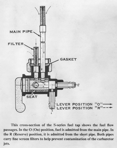
The S-series machines all use the same manually operated fuel cock, which has
three positions. When the lever points straight down, the fuel will flow through
the valve if there is more than 1/2 gallon in the tank. When the lever points to
the rear, an "S" (meaning STOP) shows on the top side of the lever. No fuel will
flow in this position. When the lever points forward, an "R" (for RESERVE) shows
on the top side of the lever. In this position, the fuel will flow until the
tank is empty. The normal flow position of the lever (straight down) connects
the three outlets to a tall, vertical, inlet pipe inside the tank. The fuel will
flow through it until the level drops below the top end of the inlet pipe. The
RESERVE position of the fuel cock lever connects the three outlets to a short.
vertical, inlet pipe inside the tank. Obviously, fuel will still flow into the
short pipe when the level is too low for the tall one.
The fuel cock lever turns a barrel valve inside the fuel cock that is sealed in
a cylinder of cork. The outer wall of the fuel cock has two holes in its upper
side; one to the tall inlet pipe and one to the short pipe. The cylindrical cork
seal has two holes that match the two holes just mentioned. The barrel valve is
hollow and has two holes through its sides. The holes are not side by side, but
are 90° apart. They align with the holes in the cork cylinder one at a time,
depending on the position of the lever. The fuel then flows down one of the
inlet pipes, through the hole in the cork seal. through the hole in the barrel
valve, through the hollow middle, and finally through the three outlets. Of
course. each outlet has a tube leading to one of the three carburetors.
REMOVING THE FUEL COCK-S-SERIES
Turn the fuel valve lever to the #0 (OFF) position and use a wrench to take off
the sediment bowl. Drain the fuel tank by turning the lever to the #2 (RESERVE)
position and holding a container under the valve to catch the flow. CAUTION:
Don't allow the gasoline to spill on the hot engine parts, which could start a
fire.
After the tank has been drained. slip the fuel lines off their fittings. Use a
wrench to loosen the nut joining the fuel valve to the threaded pipe on the fuel
tank, and then remove the fuel valve, nut. and gasket from the tank.
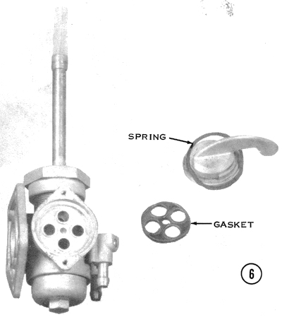
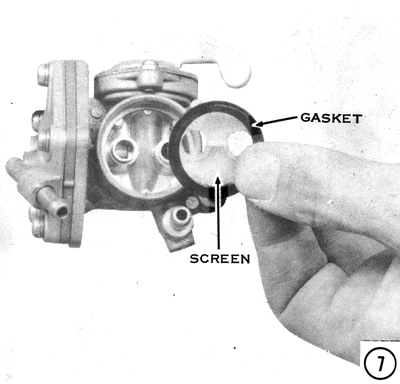
CLEANING AND INSPECTING
Clean the filters around the two inlet tubes, and use compressed air to remove
any sediment from the top of the fuel valve. Take off the sediment bowl gasket,
retainer, and filter screen. Inspect the screen for obstructions by viewing it
against a bright light. Replace the screen if it is torn or cannot be cleaned
thoroughly.
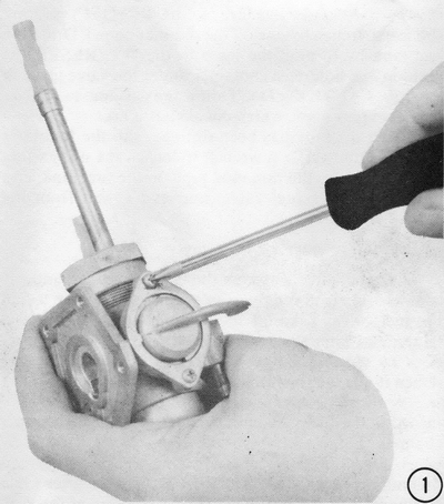
Another problem is that the cork seal may have turned in the fuel valve body,
restricting the fuel supply channel. To correct this, take out the small
setscrew which holds the lever in the fuel valve body, and then pull out the
lever. CAUTION: Don't turn the lever while pulling it out, as this will change
the position of the cork seal, if it is loose. Inspect the positions of the
holes in the
cork seal with respect to the channels in the fuel valve body. If the holes
don't line up, use compressed air to blow the seal out of the fuel valve body.
Apply gasoline-proof gasket cement to its outer surface, keeping the glue away
from the holes or inner surface. Reinstall the seal carefully, lining up the
cork seal holes with the channels in the fuel valve body. Wipe off excess cement
before inserting the lever. Let the cement dry, and then soak the fuel valve in
gasoline to shrink the cork seal before operating the fuel valve. Install the
setscrew into the fuel valve with the lever pointing toward the #1 position.
NOTE: Push the lever into the valve while tightening the setscrew, to make sure
the screw fits into the lever's retaining groove.
INSTALLATION
Position a new gasket inside the joint nut, and then thread it onto the fuel
valve by 1/4 turn. NOTE: The joint nut has both right- and left-hand threads.
CAUTION: To prevent damaging the threads, install the joint nut on the fuel
valve with the collar facing away from the valve. Hold the fuel valve against
the fuel tank, and then turn the nut onto the tank's threaded fitting, which is
a right-hand thread. Keep the fuel valve from turning while tightening the joint
nut, or else the gasket will be pushed out of its groove in the nut and leakage
will result.
Push the fuel line onto the fuel valve fitting, and use a clip to secure it.
Position the filter screen, retainer, and gasket up inside the valve, and then
install the sediment bowl with a wrench. CAUTION: Don't overtighten the sediment
bowl, or you will tear the gasket. Pour gasoline into the tank and open the fuel
valve to prevent drying out of the seal and gaskets.
The H-series Fuel Cock
The H-series machines use a different fuel cock, of an automatic,
vacuum-operated type. The lever has three positions. When the lever is straight
down, it is in the ON position, and fuel flows from the tall inlet pipe to the
three outlets, but only when the engine is running. When the engine stops, the
fuel flow stops. When the lever is pointed to the rear, fuel flows from the
short inlet, but only when the engine is running. This is the RESERVE position.
When the lever is pointed straight up, the fuel cock is in the PRIME position,
and fuel flows from the short inlet pipe to the three outlets whether the engine
is running or not. The automatic, vacuum-operated fuel cock has a disc-type
valve instead of a barrel valve, but the important feature of this fuel cock is
the diaphragm-operated needle valve that controls the fuel flow after it has
passed the disc valve.
Fuel enters the standpipe and is channeled to the diaphragm valve seat by the
lever (in the ON or RESERVE position). When the engine is stopped, this is as
far as the gasoline can travel, because the diaphragm and its 0-ring seal are
forced against the valve seat by the shutoff spring. When the engine is running,
intake port vacuum pulls the diaphragm to the left against the shutoff spring
tension, and the 0-ring seal is lifted out of the valve seat. The fuel then
passes through the diaphragm valve and fills the sediment bowl. The fuel rises
through the filter screen and then flows through the outlet to the fuel line
supplying the carburetor float chambers.
It is important to understand the vacuum circuit of the automatic fuel valve in
order to service it properly. The right-hand carburetor has a vacuum fitting
that is exposed to the vacuum and pressure pulses in the carburetor throat while
the engine is running. The vacuum hose transmits these pulses to the fitting on
the fuel valve's diaphragm cover. A check valve inside the cover cancels the
pressure pulses, and the vacuum is admitted into the diaphragm chamber. The vent
hole in the inner diaphragm cover admits atmospheric pressure to the right side
of the diaphragm, and forces it to the left against shutoff spring tension.
NOTE: If the vent hole is blocked, the diaphragm will not open properly. When
the engine is stopped, the vacuum pulses in the carburetor throat are replaced
by stable atmospheric pressure. A small pinhole in the check valve disc admits
this pressure into the diaphragm chamber and bleeds off the vacuum acting on the
diaphragm. NOTE: If the pinhole becomes obstructed, the diaphragm will remain
vacuum locked in the open position. The shutoff spring pushes the diaphragm to
the right, and the O-ring seal shuts off the fuel flow through the valve seat.
The automatic fuel valve has a priming mechanism that is used when the
carburetor float chambers empty of gasoline, such as after overhauling the
carburetors or running out of gas. By turning the lever to the PRIME position,
the diaphragm is bypassed and the fuel flows directly through as in an ordinary
fuel valve. After starting the engine, turn the lever to the ON or RESERVE
position. CAUTION: Don't park the motorcycle with the lever in the PRIME
position, or crankcase flooding may occur.
INSPECTING ON THE MOTORCYCLE
To check the fuel valve for internal air or fuel leaks, remove the sediment bowl
and the vacuum line, then install a spare length of hose on the vacuum fitting.
Hold
a container under the fuel valve and suck on the hose with the lever in the ON
and RESERVE positions. A steady flow of gasoline must come from the fuel valve.
and fuel flow must stop as soon as the suction is released. There must not be
any vacuum leakage in the diaphragm chamber nor any gasoline coming out of the
vacuum hose; either of these problems indicates a defective diaphragm, which
must be replaced. NOTE: If gasoline leaks out of the small vent hole in the
inner diaphragm cover, the spacer gasket, vent gasket, or diaphragm is damaged.
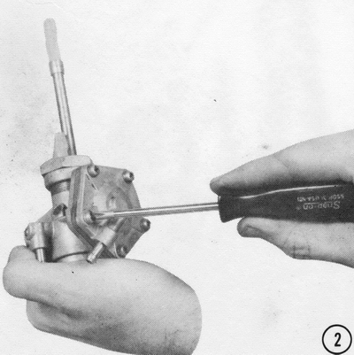
REMOVING AND DISASSEMBLING-H-SERIES
1) Turn the lever to the ON or RESERVE
position, and use a wrench to take off the sediment bowl. Drain the tank into a
container by turning the lever to the PRIME position. Slide the fuel lines and
vacuum line off the fuel valve fittings. Loosen the joint nut, and then remove
the automatic fuel valve, gasket, and nut from the fuel tank threaded fitting.
Take out the two screws holding the lever, and then lift off the lever, lever
plate, and spring ring.
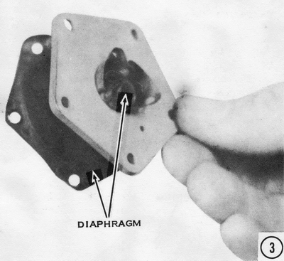
2) Loosen the five screws on the diaphragm cover a few turns at a time in a
crisscross pattern to prevent pinching the diaphragm. Lift off the cover, then
carefully separate the diaphragm and spacer from the fuel valve. CAUTION: Don't
pull on the diaphragm if it adheres to the inner cover, or you will tear it. Instead, soak the fuel valve in gasoline to loosen the diaphragm.
CLEANING AND INSPECTING
Wash the parts in gasoline and then blow them off with low-pressure compressed
air. CAUTION: Don't soak the parts in carburetor-cleaning solvent, which can
ruin the diaphragm. Inspect the valve seat surface in the inner cover for
nicks or gouging, which can cause fuel flow when the engine is stopped. Suck on
the vacuum fitting in the diaphragm cover to make sure the check valve is not
stuck; there must be no restriction. Blow into the vacuum fitting to inspect the
check-valve disc pinhole; there must be more restriction than when sucking on
the fitting, but there must also be a slow air leak into the diaphragm chamber.
NOTE: If there is no difference in restriction when blowing or sucking on the
fitting, the check valve is stuck. This can cause an erratic fuel supply to
the carburetors and poor performance. Use a straightened paper clip to loosen
the check valve disc. If the disc pinhole is blocked, use a needle to clear it.
Replace the complete fuel valve if the check valve or shutoff valve seat is
damaged.
Visually inspect the diaphragm for signs of tearing or puncture. Check the
O-ring seal for cuts or gouging, which can cause fuel flow when the engine is
stopped. Any damage to the diaphragm or O-ring seal requires replacement of the
diaphragm and spacer together. Check the inner diaphragm cover to make certain
the vent hole is clear. Inspect the lever gasket for cuts or tears which would
cause leakage around the fuel valve lever. NOTE: Damage to the lever gasket,
O-ring seal, and diaphragm is most often caused by leaving the fuel tank empty
for a long period of disuse, which results in drying out and deterioration of
these rubber parts.
ASSEMBLING AND INSTALLING
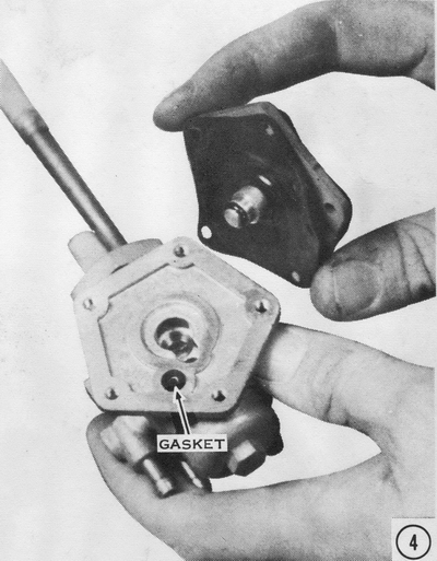
3) Wipe off any gasoline from the diaphragm covers and the diaphragm. Position
the vent gasket inside the inner diaphragm cover and smear oil around the valve
seat surface. Fold up the gasket side of the diaphragm and insert it into the
dished side of the spacer. Rotate the spacer inside the diaphragm until the vent
holes line up, as indicated by the two matching ears on the spacer and
diaphragm.
4) Position the diaphragm on the fuel valve so that the vent holes line up with
the vent gasket in the diaphragm cover.
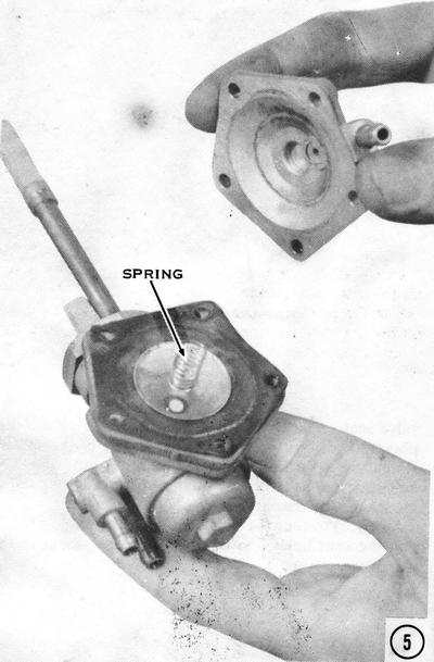
5) Install the shutoff spring over the diaphragm, and then position the
diaphragm cover so that the vacuum fitting is in line with the spacer ear.
Install the cover screws, with lockwashers, and tighten them in a crisscross
pattern a few turns at a time to prevent damaging the diaphragm.
6) If the lever gasket was damaged, install a new one and oil it to prevent
damage. Insert the lever, with spring ring, into the lever clamp plate. Install
the lever plate with the PRI mark toward the sediment bowl, and turn the lever
to the RESERVE position before tightening the two screws. CAUTION: If the
lever is installed without the spring ring, gasoline will leak past the lever.
7) Hold the nylon filter by its tab, and then position it inside the fuel valve
with the filter holes lined up with the outlets. Install the gasket next to the
filter and use a wrench to install the sediment bowl. Roll a new gasket inside
the joint nut groove, and thread the nut on the fuel valve by 1/4 turn.
CAUTION: To prevent damaging the threads, install the joint nut with the collar
toward the fuel valve. Hold the fuel valve against the fuel tank, and turn
the nut onto the threaded fitting, which is a right-hand thread. Keep the fuel
valve from turning while tightening the joint nut, or else the gasket will be
pushed out of its groove, resulting in leakage.
Install the vacuum line, with a clip, on the diaphragm cover fitting. Slide the
fuel line onto the fuel valve fittings, and then secure them with a clip.
CAUTION: Don't reverse one of the fuel lines and the vacuum line by mistake, or
else the engine will die soon after starting, from fuel starvation. If the
lever is turned to the PRIME position, the engine will be flooded through the
vacuum fitting on the carburetor. Fill the fuel tank and start the engine to get
gasoline into the O-ring and gasket side of the diaphragm and prevent their
drying out.
AIR CLEANER
There are three types of air cleaners used on Kawasaki triples. The S-series
machines all have a cylindrical paper element, which fits in a can behind the
carburetors and under the seat. The carburetors are connected to the air cleaner
by three short rubber tubes. The air cleaner has built-in baffling to silence
intake noise.
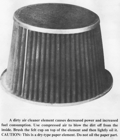
The H1's all have a conical paper element in the same general location as on the
S-series. The air cleaner can is connected to the carburetors by a one-piece
rubber molding that incorporates the three tubes to the carburetor mouths and an
air plenum chamber below the filter element. Early H1's had no provision for
silencing intake noise, but 1972 models started using a plastic air horn on the
H1B. This was not used on the H1C, but appears on the H1D, H1E, and H1F models.
The H2's all have a conical, oil-wetted foam filter. The location and air
ducting are very similar to the H1's parts. All H2's have a rubber air horn on
top of the air cleaner.
The paper-type air filters on H1's and the S-series models can be cleaned by
blowing dirt off with low pressure compressed air. If they are very dirty,
however, they must be replaced.
The H2 air filter is washable in kerosene or a parts cleaner type of solvent.
After removing the filter from its wire frame, wash it carefully and dry it
completely. Prepare a one-to-one solution of gasoline and SAE 30-weight motor
oil. Soak the filter in this solution until it is thoroughly impregnated. Let it
dry overnight and the gasoline will evaporate. leaving just the right amount of
oil distributed evenly over the foam filter element.
If the upper air filter cap is dirty, it should be brushed lightly. Rub a little
SAE 30-weight motor oil into the felt pad to restore its effectiveness.
CARBURETORS
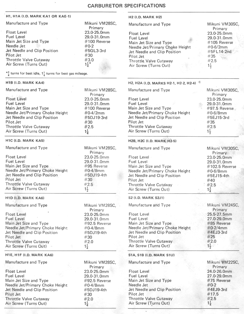
All Kawasaki triples use Mikuni VM-type carburetors. They are simple in
construction but cleverly designed to give a fuel/air ratio well matched to the
requirements of the engine under a wide variety of load and speed conditions.
This carburetor has four basic systems: a float system, pilot system, main
system, and cold-start system. The float system consists of the fuel bowl, with
a float operated fuel inlet needle valve. The fuel flows down from the tank by
gravity and into the fuel bowl. As the fuel in the bowl rises to a predetermined
level, the float pushes the inlet needle valve closed. The level of the fuel is
important to the motorcycle's performance, as we shall see.

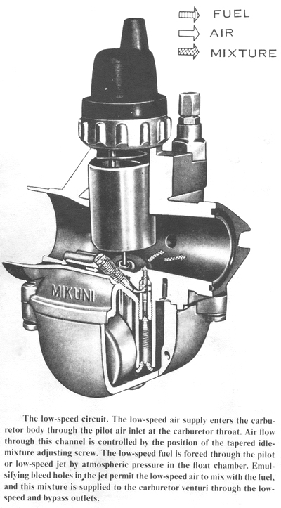
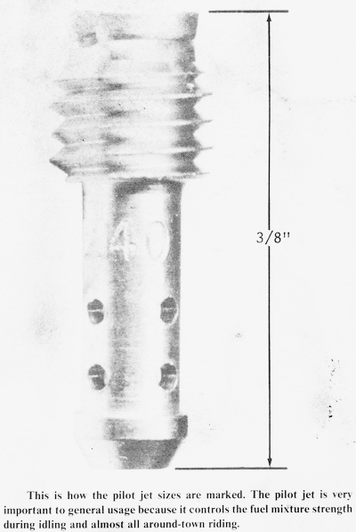
The pilot system is analogous to the idle system on an automobile. Under
low-load conditions, it supplies the fuel/air mixture the engine needs. The
pilot jet is in a tube leading from the carburetor body or mixing chamber down
into the fuel in the bowl. In the front of the carburetor throat is an air inlet
leading to a small premixing chamber above the pilot jet. Incoming air is
controlled by the air screw. Turning the air screw clockwise cuts down the
amount of air admitted, making the pilot mixture richer. Turning it
counterclockwise has the opposite effect. In the premixing chamber above the
pilot jet is an "emulsion tube," which is a small-diameter tube with holes. The
low pressure produced by the engine sucks the fuel up through the pilot jet and
into the emulsion tube. It also sucks air past the air screw and into the
premixing chamber around the emulsion tube. The air passes through the holes in
the emulsion tube and joins the fuel to make a bubbly froth or emulsion. This
mixture is drawn through a short passage and joined by more air from the
carburetor throat that comes in through the bypass hole. This final mixture
flows into the carburetor throat through the pilot outlet hole and goes into the
engine. If the throttle is lifted a little bit, the flow in the bypass reverses
and the fuel/air emulsion flows out through both the pilot outlet and the
bypass.
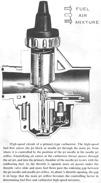
The main system comes into play from idle speed to full throttle. All the fuel
for the main system comes through the main jet. Like the pilot jet, this one is
located in a tube extending from the body of the carburetor down into the fuel
bowl. Of course it is much larger than the pilot jet. and protrudes from the end
of the tube into the very bottom of the bowl. The main jet feeds fuel to the
needle jet. Down the middle of the needle jet and partially blocking it is a
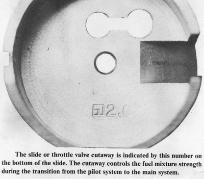
tapered rod called the jet needle. This is carried by the throttle slide, a
pistonlike valve that rides up and down in a bore in the carburetor body to
control the amount of air going into the engine. As the slide is raised and
lowered. the taper of the jet needle changes the amount of blockage of the
needle jet. This varies the amount of fuel which can get through the needle jet
and to the engine. At low speeds, the slide closes the venturi, restricting the
amount of air available to the engine. At the same time, the larger diameter
upper end of the jet needle blocks the outlet of the needle jet, allowing less
fuel to flow. At large throttle openings, the slide opens the venturi and a lot
of air can come through. Because the slide is so high, only the sharp tip of the
jet needle hangs down into the needle jet. resulting in a greater fuel flow.
When the jet needle is pulled so far out of the needle jet that the needle jet's
flow capacity exceeds that of the main jet, the total fuel flow is determined by
the main jet alone. This happens over about 3/4 throttle.
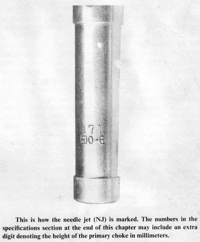
Another feature of the main system is the primary choke of the needle jet.
The primary choke is a little wall from 2 to 8mm high on the front of the needle
jet opening, extending tip into the carburetors venturi. The primary choke acts
in conjunction with a tiny fuel reservoir around the top of the needle jet and
an air passage to the reservoir from the mouth of the carburetor. Together they
act to keep the fuel mixture lean at low power outputs to help the engine run
more smoothly. At high throttle openings, they enrich the mixture to protect the
engine from overheating and possible seizure. The higher the primary choke is.
the greater the combined effect.
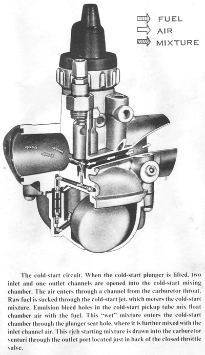
The fourth system of the Mikuni VM carburetor is the cold-start mechanism. This
is a special system that takes the place of the choke on an automobile
carburetor. When activated, it supplies an extrarich mixture to the cold engine
for starting. An emulsion tube extends into a well in the fuel bowl. At the
bottom of the well is a small, fixed, brass cold-start let. A large air passage
leads from the mouth of the carburetor to a mixing chamber on the side of the
carburetor body at the rear. A large, flat-fronted valve in the chamber closes a
fuel passage that conies up from the emulsion tube. To start a cold engine, the
cold-start valve is lifted with the throttle closed. The engine sucks fuel
through the cold-start jet, up the emulsion tube (air is supplied by the air
space above the fuel in the bowl), and into the mixing chamber. There it is
joined by more air, and the mixture is drawn down a passage which empties into
the carburetor throat downstream from the throttle slide. The throttle slide
must be closed for the cold-start system to be effective.
OVERHAULING THE CARBURETOR
See the engine disassembly section of Chapter 4, Engine Service, for carburetor
removal. Because of the possibility that gasoline will spill out of the
carburetors while you are disassembling them, work on a surface that will not be
harmed by it. CAUTION: Fire danger is extreme. Do not smoke while working on
the carburetors or work near an open flame until the carburetors have been
completely disassembled and dried.
DISASSEMBLING
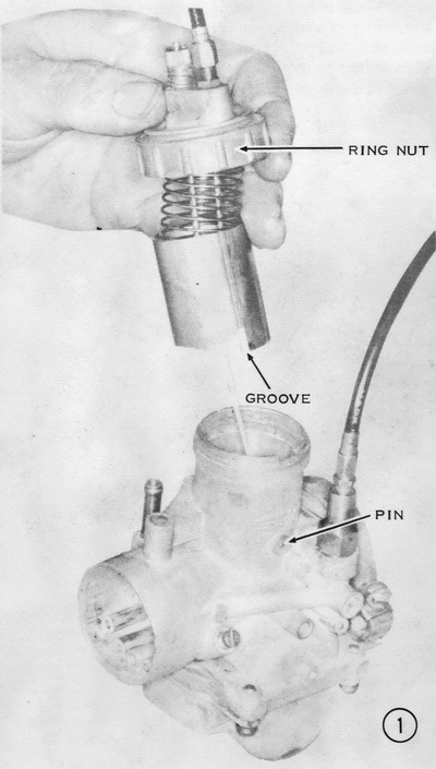
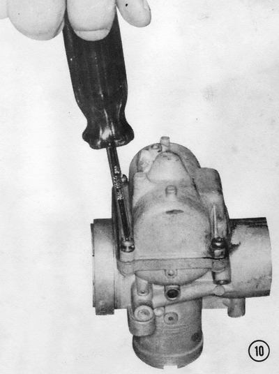
1) Unscrew the ring nut, then lift the throttle slide assembly out of the
carburetor body.
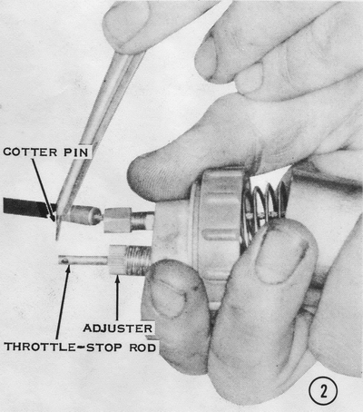
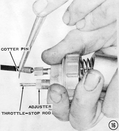
2) Push together the ring nut (with the carburetor cap in it) and the throttle
slide assembly to compress the slide spring. This will cause the throttle stop
rod to protrude from the idle speed adjuster. Remove the cotter pin from the end
of the throttle stop rod. The throttle stop rod will fall out of the bottom of
the slide.
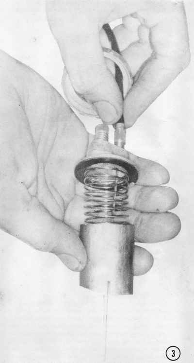
3) Push the throttle cable sheath down into the adjuster while holding the
throttle slide and the carburetor cap aligned as shown. Disengage the cable
nipple from the keyhole-shaped hole in the center of the throttle slide. There
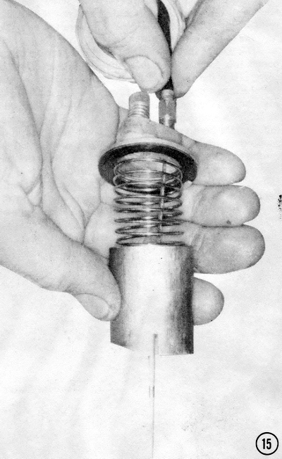
may be a needle retainer in the slide under the spring, in which case the spring
must be compressed separately and pulled completely out of the slide to allow
the retainer to move far enough to let the cable nipple move to the large end of
the keyhole-shaped hole in the slide.
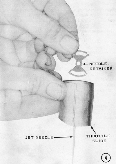
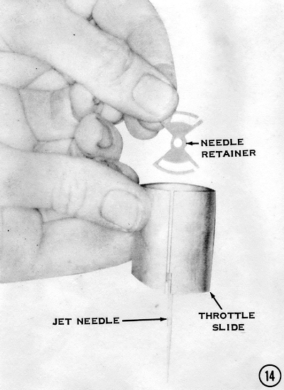
4) Pull out the needle retainer, then push the needle out from the bottom.
CAUTION: Do not remove the small E clip on the top end of the needle. If the
E-clip were accidentally moved to a higher notch, the carburetor would supply a
leaner mixture, which would cause overheating, detonation, and engine seizure.
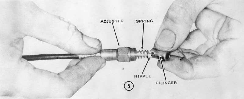
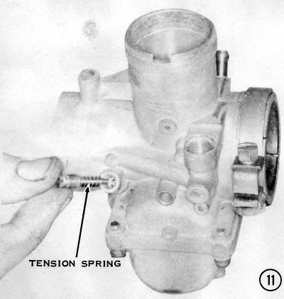
5) Use a 12mm wrench to remove the cold-start cable adjuster from the carburetor body. Compress the spring enough to disengage the cable nipple from the plunger. The spring and adjuster will now slip off the end of the cable.
6) Unscrew the air screw, and remove it and the spring from the carburetor
body.
7) Remove the four float bowl screws. If there is an overflow tube bracket held
on by one of the screws, note on which corner of the bowl it goes to speed
assembly. Lift off the bowl and remove the gasket between it and the carburetor
body.
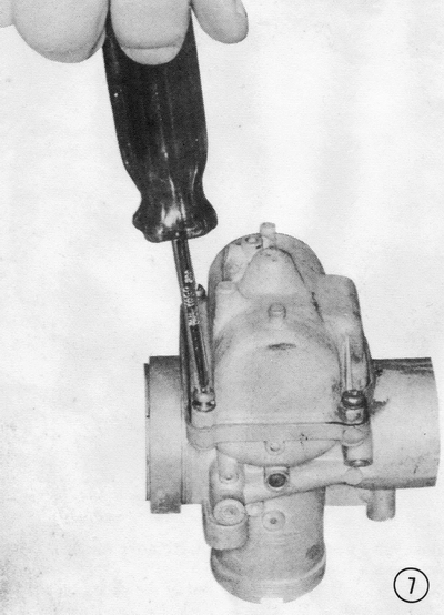
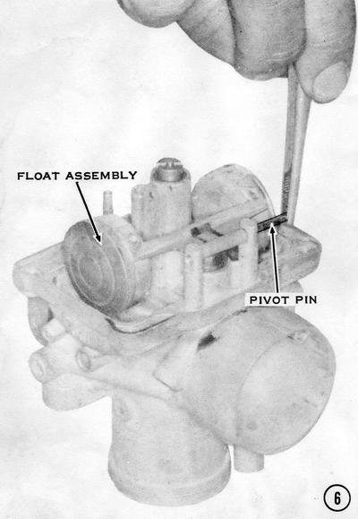
8) Slip out the float pivot pin, then remove the float. Use a small flat-bladed
screwdriver to remove the pilot jet. Use as large a flat-bladed screwdriver as
possible to remove the main jet. CAUTION: These jets are brass and rather
soft. Be careful not to let the screwdriver ruin the slot. Do not push wires or
small drills through the jets. Turn the carburetor body right side up and
catch the
float valve needle as it falls out. Remove the float valve seat with a 10mm
socket wrench.
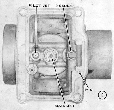
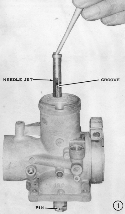
9) Lift the needle jet out of the carburetor body from the top. It may be
necessary to tap it from the bottom with main jet removed. Do not damage
threads!
CLEANING AND INSPECTING
Soak all carburetor parts, except those made of rubber, in solvent or a
commercial carburetor-cleaning solvent. Rinse the parts thoroughly in hot water
to remove the solvent. Use compressed air to blow out all jets and passageways.
Inspect all jets and passageways for deposits caused by stagnant gasoline.
Check the float valve needle and seat for pits or grooves. Submerge the float
assembly, and then shake it to listen for gasoline, which would indicate a leak.
NOTE: A leaking float causes high fuel levels, with consequent rich fuel-air
mixtures and flooding. Dark scratches on the brass floats indicate contact
with the carburetor body caused by an incorrect float level adjustment. Check
the floats for a convex shape, which is normal. Concave floats have been
collapsed by using compressed air on an assembled carburetor, and they will
result in excessively rich fuel-air mixtures. Insert the float hinge pin in the
carburetor body and check for a snug fit.
Compare the markings on the main jet, jet block, jet needle, low-speed jet, and
throttle valve cutaway against specifications.
Inspect the throttle slide for wear on its outer surface. If the plating has
worn through, replace the throttle slide. NOTE: A worn throttle slide is
evidenced by a clicking sound at low throttle openings. Insert the throttle
slide in the carburetor body and check for free movement. If binding is evident,
replace the carburetor. CAUTION: A sticking throttle slide can cause loss of
control from a runaway engine.
Roll the jet needle on a flat surface to check for bending, and inspect the
tapered section for nicks or wear. Make sure the clip is tight in the jet needle
groove and the retainer is not bent or broken. NOTE: A loose jet needle
flutters in the jet block and causes erratic engine operation at part-throttle
openings.
Check the rubber seal in the end of the cold-start plunger for cracking or
deterioration. Insert the plunger into the carburetor body and check for free
movement without excessive play. To inspect the plunger for leaking in the off
position, install the plunger, spring, and nut in the carburetor body. Wrap tape
around the pickup tube, and then blow into the tube. There must not be any
leakage past the plunger seal, which would cause flooding at low throttle
openings. If leakage is evident, check the plunger bore in the carburetor body
for damage and inspect the plunger seat for nicks.
To check the carburetor fuel channel, hold a finger over the float valve hole,
then blow into the fuel line fitting. Leakage is caused by a porous carburetor
casting; therefore, you must replace the carburetor.
The fiber insulating sleeve of a spigot clamp-type carburetor must not be worn
or cracked. NOTE: On H2 models, check the rubber socket on the cylinder
intake flange for poor bonding to the metal flange, which can result in an air
leak. CAUTION: A leaking carburetor-to-manifold connection results in
excessively lean air-fuel mixtures, with consequent piston seizure and engine
overheating.
Inspect the throttle and cold-start cables for fraying or corrosion. Make sure
the cable action is free of binding. Make sure the throttle stop rods are
straight by rolling them on a flat surface. CAUTION: A bent or nicked
throttle stop rod can cause the carburetor to stick at wide-open throttle.
ASSEMBLING
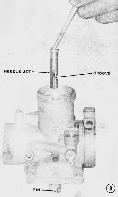
1) Drop the needle jet into the carburetor body from the top. The notch in the
side of the jet fits onto a pin in the body near the bottom, as shown. NOTE:
The pin must be tight in the carburetor body.
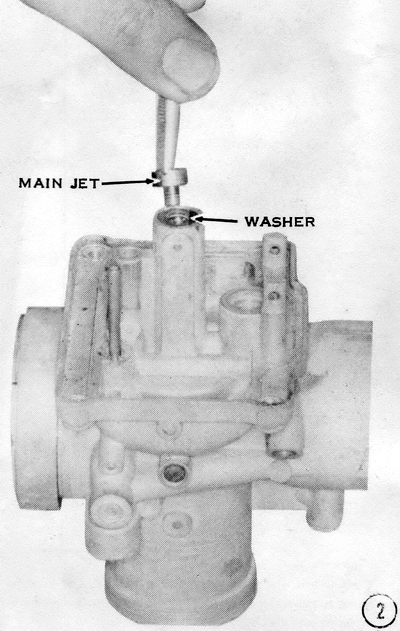
2) Turn the body over. Put the washer on the bottom end of the needle jet, and
then thread the main jet into the bottom of the needle jet. CAUTION: Be sure
the main jet is a reverse-type, round-headed jet. A hex-head main jet has
different-sized threads and can strip the threads in the needle jet. Check the
size in the specification table in the Appendix. Too small a main jet can cause
major engine damage from overheating. Too large a main jet will cause excessive
exhaust smoking, high gasoline consumption, excessive emissions, and poor
high-speed running.
3) Tighten the main jet to 17 lb-ins. CAUTION: Be sure the tip of the screwdriver fits the slot in the jet. The main jet is soft brass and can be damaged easily by using too narrow a blade or by overtightening. After tightening the main jet, look into the air jet passage in the mouth of the carburetor to check the alignment of the needle jet air hole. CAUTION: If the air hole is blocked or masked, midrange and high-speed operation will suffer unless the needle jet is replaced.

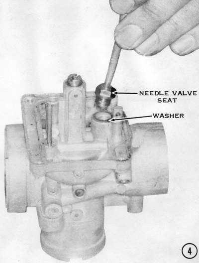
4) Check that the fuel inlet passage is clear, and then install the needle valve
seat with its washer. Tighten the seat securely. CAUTION: Do not overtighten
or the carburetor body will be damaged.
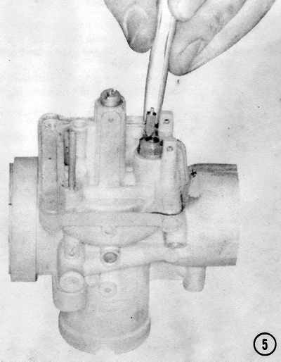
5) Drop the needle valve into the seat with the sharp end down. Suck on the fuel
line while holding the valve against the seat, to check for leaks that will
cause flooding or fuel overflow. Leaks can occur at the needle and seat and
through casting flaws in the carburetor body.
6) Position the float assembly as shown, and then slide the pivot pin into
place. Note that the soldered tangs on the floats point toward the main jet.
CAUTION: Be sure the floats have not been crushed or bent so as to interfere
with the carburetor body or float bowl. The pivot pin must be a fairly snug fit
in the carburetor body posts or the float valve's performance will be erratic.
Hold the carburetor right side up and check that the float does not drop far
enough for the needle valve to fall out of its seat. CAUTION: If the needle
valve falls out in operation, the carburetor will immediately overflow, flooding
the engine inside and out, which is a dangerous fire hazard. The float on early
models cannot be adjusted and must be changed for one with less drop. Later
models have an adjusting tab. which can be bent to obtain a maximum float drop
of 20mm.
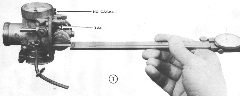
7) To measure the float level, rest the carburetor body on a horizontal flat
surface, with its air intake pointing straight up. Tip it back until the float
arm just touches the valve tip. Measure the distance from the float bowl gasket
surface (without a gasket) to the outermost edge of the float. which must be as
specified in the Appendix. If it is incorrect, bend the tab that bears on the
end of the needle valve. NOTE: Too high a float level will cause major engine
damage from overheating. Too low a float level will cause excessive exhaust
smoking, high gasoline consumption, excessive emissions, and poor highspeed
running.
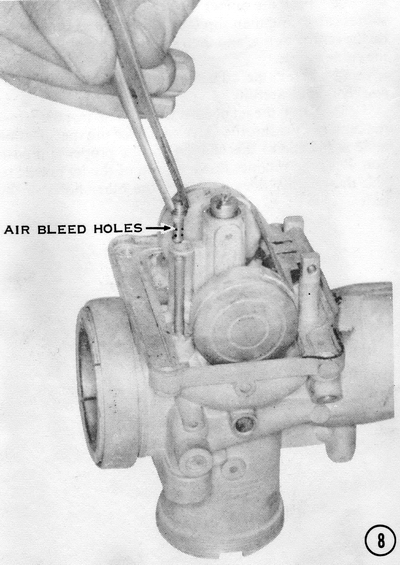
8) Drop the pilot jet into the tube behind the main jet, with the bleed holes
down. Check that the pilot air and fuel passages in the carburetor body are
open. CAUTION: Clogged pilot system passages can cause poor low-speed
running. If they are blocked completely, the engine will not idle at all. The
bleed holes in the jet must also he free of debris. CAUTION: When replacing
pilot jets, be sure they have ISO threads. This is commonly indicated by a punch
mark on the face of the jet near the screwdriver slot. If a jet with incorrect
threads is used, the carburetor body will be damaged. See the beginning of
Chapter 4, Engine Service, for a complete explanation of ISO threads.
Carefully tighten the pilot jet with a small screwdriver.
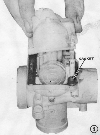
9) Install a new gasket so that the eyelet on the gasket fits over the tube for
the cold-start jet. Check the inside of the float bowl to be sure the brass
cold-start jet is in the bottom near the starter reservoir tube. The brass
overflow tube must be tight in the bowl. CAUTION: If the overflow tube
loosens or falls out during operation, gasoline will run out of the bowl,
causing a fire hazard. Check that the air vent in the carburetor body is
clear. H1 carburetors have an extra vent that opens into the mouth of the
carburetor, which must also be open. CAUTION: If all the air vents are
stopped, the float chamber will be under pressure when the fuel cock on the tank
is opened. This will force the gasoline through the needle jet and into the
venturi of the carburetor, creating a fire hazard or a severely flooded engine.
Position the float bowl on the gasket.
10) Fasten the float bowl in place with four screws, each with a lockwasher.
Don't forget the overflow tube holder on H2 and S-series carburetors, which goes
on one of the screws closest to the engine. Tighten the screws evenly to prevent
distorting the fuel bowl.
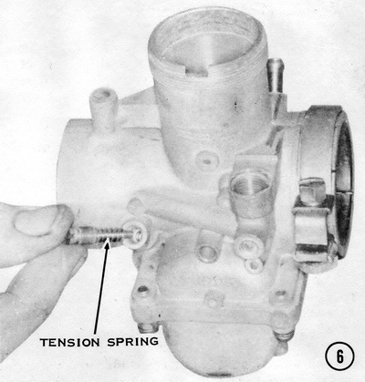
11) Screw in the air screw with its tension spring. CAUTION: Do not tighten
this screw excessively; bottom it lightly to prevent damaging the seat in the
carburetor body, which would make an idle mixture adjustment difficult. This can
only be cured by replacing the carburetor assembly, or the body, if one is
available.
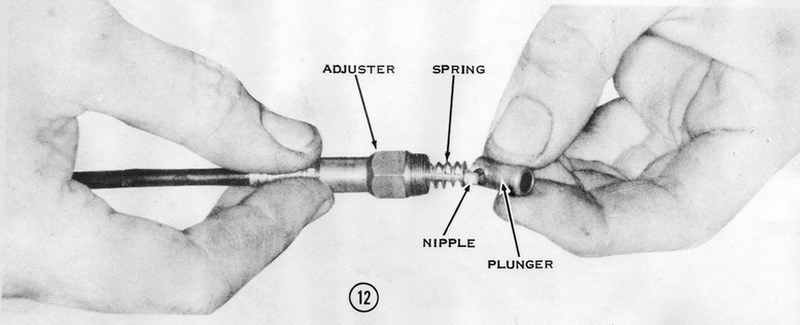
12) Push the rubber dust cover over the end of the starter cable, and then slip the adjuster on as shown. Put on the return spring, and then slip the valve plunger over the cable nipple.
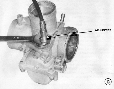
13) Screw the adjuster into the carburetor body and tighten it carefully.
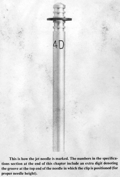
14) Drop the jet needle. with its clip installed, into the center of the
throttle valve slide. See the specification table at the end of this chapter for
the proper clip position. Push the retainer down on top of the jet needle so
that the retainer does not cover the other holes in the slide.
15) Insert the slide-return spring into the slide and push the throttle cable
through the ring nut and through the adjuster in the carburetor top. Position
the carburetor top against the return spring. Now push the cable nipple through
the double hole in the slide. NOTE: Be sure the gasket is in place. The
cable nipple will hook into the other side of the double hole when released. Now
use a pointed instrument to rotate the needle retainer until it is in a position
to prevent the cable from slipping back into the large side of the double hole.
NOTE: Some models use a retainer with a small tab that fits into the double
hole to prevent the cable from slipping out.
16) On H1 and S1 models only, slip the throttle stop rod up through the last
hole in the throttle valve slide. The rod should extend through the slide,
inside the spring, and through the idle adjuster screw on the carburetor top as
shown. Insert a small cotter pin in the hole in the end of the rod to secure it.
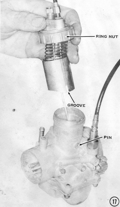
17) Install the completed slide assembly into the throttle bore of the
carburetor body. The groove in the slide fits on the pin in the side of the bore
to prevent the slide from rotating. The needle goes into the needle jet. The key
in the carburetor top fits the notch in the body, as shown in Step 15). Screw
the ring nut on finger tight. CAUTION: Be sure the gasket stays in position.
If the gasket slips out of position, it could prevent the throttle slide from
moving freely. If it loosens during engine operation, it can be tightened by
tapping lightly on the ridges with a screwdriver and a mallet.
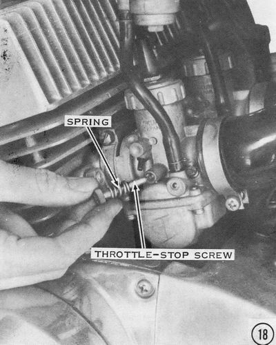
18) Install the side throttle-stop screw, with its tension spring, on H2's, S2's, and S3's. Screw it in until it just lifts the slide. CAUTION: If it is screwed in all the way, the engine will race when started.
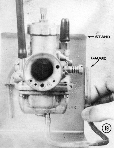
19) Even though the float level has been set on the bench. this does not
guarantee that the fuel level will be correct. It is the fuel level that
actually determines how rich the mixture will be. To measure the fuel level,
drill a small hole in the bottom of an old float bowl and thread it to accept a
small brass fitting, onto which a neoprene tube should be fitted as shown.
Though the illustration shows the carburetor mounted on a test stand. the level
can be similarly checked on a motorcycle. Find the fuel level for your machine
in the specification table at the end of the chapter. That level is the distance
in millimeters from the center of the carburetor bore to the level of the fuel
in the bowl when the float valve shuts off the fuel flow from the tank. Measure
the distance on your carburetor, and then make a scratch on the side of the
float bowl at the proper fuel level. Turn the fuel cock ON and hold the neoprene
tube up beside the float bowl. The fuel in the tube should rise to the scratch
mark. If it is too high, the float level must be raised. If it is too low. the
float level must be reduced.
TUNING THE CARBURETORS
The procedure for adjusting the idle speed is covered in Chapter 2, Tuning for
Performance. The carburetor settings listed in the specification table at the
end of this chapter are the manufacturer's recommendations for general usage.
Because conditions of operation may differ, it may be necessary to experiment
with the carburetor adjustments and tuning to obtain peak engine performance
and/or best fuel economy. This section explains how to tune the carburetors for
each mode of operation. Before changing the jetting of the carburetors, be sure
the ignition system is in good condition and the engine is properly timed. The
carburetors must also be properly synchronized.
SYNCHRONIZING THE CARBURETORS
In order for the engine to run smoothly and deliver the best performance and
fuel mileage, all three carburetors must act together. They must be synchronized
so that all three throttles lift the same amount at the same time, so that all
three pilot systems and main systems are working in unison.
To synchronize the carburetors, first warm the engine to operating temperature,
and then switch it off. Loosen the throttle cable adjuster at the twistgrip to
get as much cable slack as possible. This moves the sliding block that carries
the four lower cables (one to each carburetor and one to the oil pump) all the
way to the bottom of the cable junction box. Shorten the cable adjusters on the
carburetor caps all the way. Remove any cable clips from the adjusters.
Now remove the air pipes from the mouths of the carburetors. Set all three air
screws to the setting recommended in the specification section at the end of
this chapter. Lower all three throttle slides as far as they will go, by turning
the throttle stop screw or adjuster. On H2's, S2's, and S3's, turn the throttle
stop screw counterclockwise; on H1's and S1's, clockwise. Feel with your fingers
or use a mirror to see that all three throttle slides are at the bottom of their
travel. Turn each throttle stop in the opposite direction until each
slide just begins to lift, and then make one additional turn. This will
synchronize all three carburetors at a slow idle.
Start the engine. If it will not run, turn each throttle stop exactly one more
turn to speed up the idle slightly. To increase engine idling speed to
specifications, turn all three throttle stops 1/4 turn at a time in the same
direction, until the idle is constant at 1,100 to 1.300 rpm.
If you have access to a Uni-Syn or similar air-speed sensing tool, hold it
against the mouth of each carburetor in turn and adjust the throttle stops until
the ball is lifted the same height on each carburetor. Then turn all three
throttle stops 1/4 turn at a time in the same direction until the idle is
constant at 1,100 to 1,300 rpm. Switch off the engine.
Lengthen each cable adjuster on the carburetor cap until the cable sheath has
1/16" free play. Now turn the cable adjuster at the twistgrip until the grip
also has 1/16" free play. While turning the twistgrip back and forth. check with
your fingers or a small mirror to be sure that
all three throttle slides start to lift at exactly the same time. Replace the
air pipes and any dust covers and cable clips that were removed.
There are a couple of alternative carburetor synchronization methods offered below that may offer greater precision:
ALTERNATIVE SYNCHRONIZATION METHOD 1:
1) First back off the idle screws until they don't touch the slides.
2) Carefully screw each one in until the screw just barely touches the slide.
3) Turn in each screw the exact same amount, until you get your target idle number. If you don't do this first, the little variance you get when setting the idle screws will affect slide height and the sync will not be "spot on".
4) Make sure you have slack in the cables.
5) Put your middle finger of your left hand on the center slide, and your thumb (left hand) on the right slide. Turn the throttle very slowly and feel if the slides lift at the same time. If not, adjust one or the other cable so they do.
6) Snap the throttle a couple of times to make sure the slides are setting in well, and tighten the cable lock nut and recheck.
7) Move your thumb to the center slide and your middle finger to the left carb. Adjust the LEFT carb till it lifts exactly with the center.
8) Snap the throttle again and make sure the lock nut is tight (tightening the lock nut will change the slide height).
9) Open throttle until slide is even with top of carb throat. Feel that all slides are at the same position.
10) Take out any extra slack in the cable, AND check the oil pump for correct setting.
The finger method can tell movement in thousands of an inch (just say very accurate). Set the sync from idle, because that is where it is most important.
ALTERNATIVE SYNCHRONIZATION METHOD 2:
1) Find a smooth round pin about 3/8" or 10mm dia. (the shank of drill bit works well).
2) Remove air box/filters.
3) Back out slide stop (idle adjustment) screws.
4) Set throttle lock or set throttle adjuster at the grip so the pin will just lightly drag as it is inserted in the carb throat under the slide cutaway of one carb.
5) Set the other carbs so they offer the same resistance when the pin is inserted by setting the cable adjuster at top of each carb.
6) Release throttle lock or reset throttle adjuster at grip insuring that slides on all carbs will fully bottom out and throttle grip has 2-3mm play.
7) Set air and idle adjustment screws for best idle.
As a final check to insure all idle adjustment screws are set the same, insert a nail, spoon, or long toothpick under each slide without altering slide position. As the grip is turned the ends of all three should tip at the same time. Readjust idle screws as required.
TUNING THE IDLE AND LOW-SPEED MIXTURE (IDLE TO THROTTLE)
To tune the carburetor properly for idling and low-speed running, you will have
to adjust the pilot system. The principal adjuster of the pilot system is the
air screw. First, set all three air screws to the specification given at the end
of this chapter. Now synchronize all three carburetors and set the idle speed,
as described above and in Chapter 2, Tuning for Performance. With the engine
idling, turn all three air screws in or out 1/4 turn. Listen to the exhaust and
note any change in the firing pulses. Place your hand one inch from the ends of
the mufflers to feel the exhaust pulses. Turning the air screws clockwise makes
the mixture richer, turning them counterclockwise makes it leaner. If the engine
begins "four-stroking," that is, firing on every other stroke instead of on each
stroke, the mixture is too rich. If the exhaust note is very uneven or
irregular, the mixture is too lean.
Some other signs of an excessively lean idle mixture are hesitation and poor
throttle response when accelerating from idle, overheating when the bike is
ridden at slow speeds, heavy detonation when the bike is ridden at highway
speeds, a marked idle speed increase (more than 300 rpm) when the engine is hot,
and having the engine take a long time to idle down after a high-speed run.
Some signs of an excessively rich idle mixture are four-stroking and sputtering
at an idle, fouling the spark plugs when riding at slow speeds. and excessive
fuel consumption.
Generally speaking, for better gas mileage and smoother running around town,
turn the air screws out 1/4 turn from the specified setting. unless detonation
is evident at highway speeds. For better throttle response, better low-end
torque, and easier starting on cold mornings, turn the air screw in 1/4 turn,
from the specification. Of course the standard setting is given in the
specification table.
The final idle mixture adjustment should be no more than 1/2 turn from the
specified setting. If it is, check for a clogged pilot jet, a restricted pilot
air channel, an obstructed low-speed outlet in the carburetor throat, or an air
leak at the carburetor mounting spigot or flange. NOTE: Turning the air screw
has an effect similar to changing the size of the pilot jet. If the best air
screw adjustment is more than 1/2 turn from the specified setting, the pilot jet
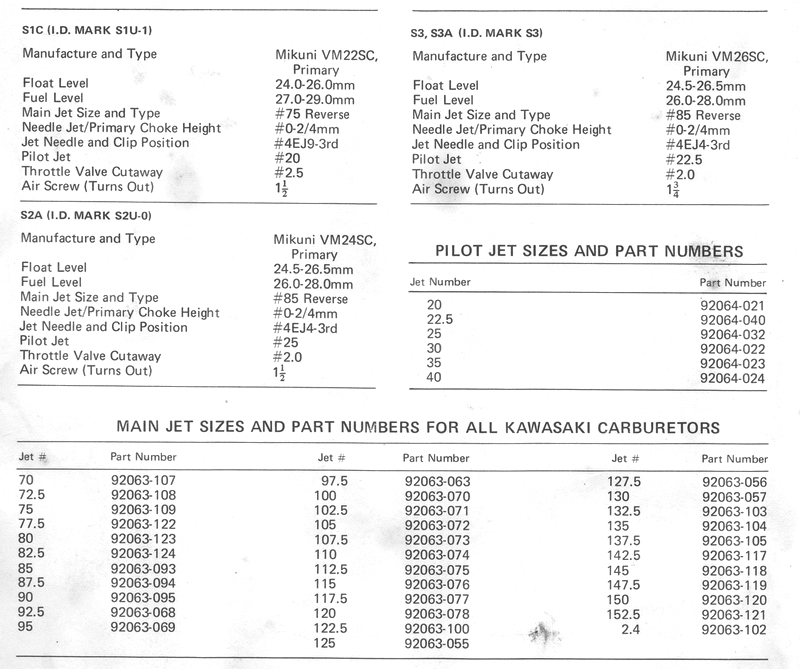
should be changed instead. If the air screw is 1/2 turn (or more) clockwise from
the recommended setting, change the pilot jet for one with a number that is five
higher. For example, if the carburetor has a #25 pilot jet standard, replace it
with a #30. If the air screw is 1/2 turn (or more) counterclockwise from the
recommended setting, change the pilot jet for one with a number that is five
lower, i.e., #25 to #20. There is a listing of available pilot jets and their
Kawasaki part numbers at the end of this chapter in the specification section.
CAUTION: Don't lean the pilot mixture enough to cause detonation at highway
speeds. Detonation will cause extensive damage to the pistons, rings, crankshaft
bearings, and spark plugs.
NOTE: Each carb must be ADJUSTED for optimum idle
via AIR SCREW adjustment.... seeking the point where idle rpm for that cylinder
is highest. That is the point where the fuel/air mixture is optimum at idle rpm.
Starting from scratch, unless you're extremely lucky, there is no "balance"
between cylinders or carbs.... one cylinder will be pulling the other two. When
this condition exists ONLY the carb on the pulling cylinder will respond to
adjustment. Setting the idle stop to insure that the "pulling" cylinder carb is
in control of idle rpm will then allow adjustment of that carb to be seen in rpm
changes. An alternative is to pull the plugs of the cylinders not being adjusted
so it would be apparent which cylinder is "pulling". If, using this method, an
air screw has no effect on idle speed, something is wrong.
TUNING THE MIDRANGE MIXTURE (1/4 TO 3/4 THROTTLE)
The fuel mixture in the midrange mode is changed by moving the clip on the top
end of the jet needle. For most usage the standard clip position is best. The
grooves in the top end of the needle are numbered from top to bottom, #1 to #5.
For high-altitude riding, the needle may be lowered to lean the mixture by
moving the clip to a lower-numbered groove; for instance, from groove #3 to #2.
For riding in cold, damp weather at sea level, the mixture may need to be
enriched for best running by raising the needle; for example, moving the clip
from groove #3 to #4.
If the engine hesitates and/or backfires when accelerating from 1/2 throttle,
the midrange mixture is too lean and the jet needle should be raised (move the
clip to the next-higher-numbered groove). This will allow more fuel to flow
between the jet needle's tapered section and the orifice of the needle jet.
If the engine is sluggish and stutters when accelerating at 1/2 throttle in high
gear, the midrange mixture is too rich. The jet needle should be lowered to
restrict the orifice of the needle jet. This reduces fuel flow (leaner mixture)
for an equivalent throttle opening. Take the clip out of its present groove and
move it to a lower-numbered groove. CAUTION: Do not lean the midrange too
much or detonation will result.
If the midrange mixture is not satisfactory after adjusting the jet needle,
check to be sure that the needle jet is tight in the carburetor body, that the
float level is correct, that the primary air passage is open, and that the jet
needle clip is in place. If the engine has over 10,000 miles on it, check the
center section of the needle for wear. If it is shiny, it has worn against the
needle jet because of engine vibration. Both the needle and the jet must be
replaced to guarantee like-new performance.
TUNING THE HIGH-SPEED MIXTURE (3/4 TO FULL THROTTLE)
The fuel mixture at high speeds and large throttle openings is controlled by the
main jet. NOTE: The main jet is not effective until the area between the end
of the jet needle and the inside of the needle jet is greater than the area of
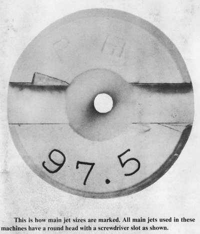
the main jet opening. The size of the main jet is marked on it. The number
is a code for the diameter of the opening in the jet; the larger the opening,
the higher the number and the richer the mixture at full throttle. All Kawasaki
triples use reverse-type main jets. They have round heads with a screw slot.
CAUTION: Do not use hex-headed main jets in these carburetors because the
threads are different, which will strip the threads in the needle jet.
To test the main jet, accelerate momentarily at full throttle in high gear at
about 50 mph. If the main jet is too small (lean) or too large (rich), the
engine will not respond well at full throttle and will regain power only when
the throttle is closed to the 3/4 position (which reactivates the midrange
system).
If the main jet is too large, full-throttle performance will be sluggish and the
exhaust note will be stuttering. Inspection of the spark plugs will show a dark
brown or sooty black color on the insulators. NOTE. These indications can
also be caused by too cold spark plugs or retarded ignition timing. Install
a main jet with the next size smaller number for a leaner mixture. Check the
list of main jet sizes and part numbers at the end of this chapter in the
specifications section. If there is still no improvement. check for a dirty air
cleaner, an obstructed air cleaner inlet, or clogged muffler baffle tubes.
If the main jet is too small. the engine may backfire or hesitate and accelerate
in lurches when the throttle is opened fully. The spark plug insulators will be
white or grayish white. Too lean a mixture will cause overheating, and if the
condition is excessive, small flecks of aluminum will be evident on the spark
plug insulators. NOTE: These indications can also be caused by too hot a
spark plug or overadvanced ignition timing. A main jet that is too small
will cause detonation at full throttle which sounds like static electricity. It
is not the same as the "pinging" sound made by an automobile engine running on
too low an octane rated gasoline. CAUTION: If detonation is heard at full
throttle, back off the throttle immediately or major engine damage will result.