Triple Maintenance Manual
Section 6 - Frame & Running Gear Service
Chapter 6
Frame and Running Gear Service
Because the rider's safety is so dependent on the integrity and reliability
of the motorcycle frame and running gear, regular maintenance and inspection are
required. When repair is undertaken, care and attention to detail must be
exercised to insure that the motorcycle is roadworthy after servicing. Before
test riding the machine, make sure you have installed all cotter pins, spring
clips, and locknuts on all critical running gear components: frontend rear-axle
nuts, rear brake panel torque link bolts and pins, brake linkages, and chain
adjusters. Inspect the front and rear brakes for proper adjustment and safe
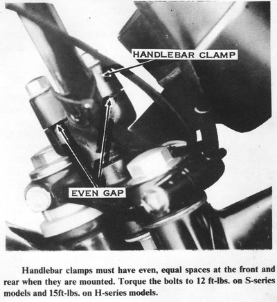
operation. Check the handlebar clamp bolts for tightness. CAUTION: Loose
handlebar clamps will permit the handlebar to rotate forward during hard
braking, resulting in a serious loss of control.
The most frequently performed service on the running gear is everyday
maintenance such as adjusting the chain and brakes and inspecting tire pressure.
Preventive maintenance, which is required at longer intervals, has to do with
periodically inspecting wheel alignment, tightening spokes, adjusting the
steering head bearings, changing the front fork oil, inspecting the brakes, and
tightening bolts and nuts.
If the motorcycle is involved in an accident, carefully inspect the frame for
cracks and misalignment. In the event of structural damage, replacement of the
frame is necessary. CAUTION: Reliable frame repair is an extremely difficult
job. Welding, heating, or straightening the damaged section can result in a
weakened frame structure.
HANDLEBAR
The only service for the handlebar is straightening or replacing it. If the
handlebar is bent more than 2", it must be replaced. CAUTION: A straightened
handlebar may be so weak that it will break while riding. To straighten a
slightly bent handlebar, slip a 4' length of pipe over the handgrip. Wedge the
front wheel between two rigid uprights, then force the handlebar back to its
original shape.
REMOVING
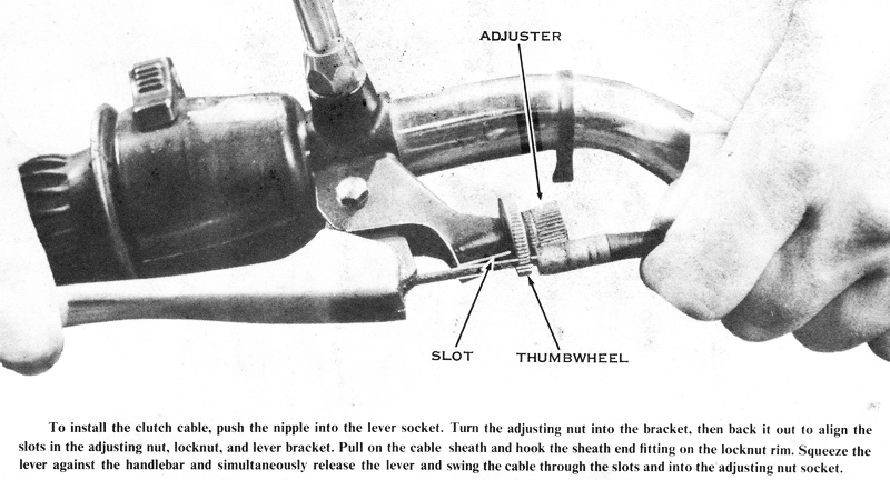
To disconnect the front brake and clutch cables, turn the adjuster all the way
in until the slots in the locknut and the adjuster line up with the slot in the
lever bracket. Compress the hand lever, then pull on the cable sheath while
releasing the lever. Swing the cable out through the slot and drop the cable
nipple out of the socket in the hand lever.
Remove the screws holding the left-hand switch case together, and then lift the
case halves from the handlebar. Remove the bolts that clamp the master cylinder
to the handlebar, and cradle the master cylinder on top of the headlight on a
rag.
Loosen the screws holding the right-hand switch case together, but do not remove
them. While holding the handlebar up so it can't fall on the fuel tank, remove
the four handlebar clamp bolts and the clamp caps. Now move the handlebar to the
left to allow the right-hand switch case and the twistgrip to slide off the end
of the handlebar.
Unscrew the mirrors from the clutch and front brake lever brackets. To remove
the clutch and front brake lever brackets, loosen the bolts, and then slide them
off each end of the handlebar. Of course the left handgrip must be removed
before the clutch lever bracket. If it will not slide off, pry it away from the
handlebar with a screwdriver, and drip gasoline or solvent between the grip and
handlebar to lubricate it so that it can slide off easily. If you intend to
replace the left handgrip, the old one should be slit lengthwise with a sharp
knife to remove it.
INSTALLING
Before installing a new handlebar, make sure it has the same outside diameter as
the stock handlebar, 7/8". CAUTION: Never install a handlebar of a
nonstandard diameter, because loss of control can result from the handlebar
slipping in the clamps during hard acceleration or braking. NOTE: If a
custom handlebar with more height or width is installed, you will have to
install longer control cables and hydraulic lines at the same time. Check your
local and state ordinances for maximum and minimum handlebar height and width.
Slip the clutch and front brake lever brackets onto the ends of the handlebar.
Lubricate the right end of the handlebar with grease. Holding the handlebar over
the tank, slip the right switch case and twistgrip onto the right-hand end of
the handlebar. Hold the handlebar in position and install the handlebar clamp
caps and bolts. Rotate the handlebar to your preference and tighten the clamp
bolts to 12-15 ft-lbs. of torque.
Assemble the halves of the left-hand switch case on the left end of the
handlebar. Lubricate the left-hand grip with gasoline or solvent, and then slip
it onto the left end of the handlebar. Push the left-hand switch case against
the left-hand grip. then tighten its screws securely. Push the twistgrip as far
onto the right end of the handlebar as possible without the twistgrip rubber
touching the end of the handlebar, and then tighten the screws so that the
switches are in a convenient position.
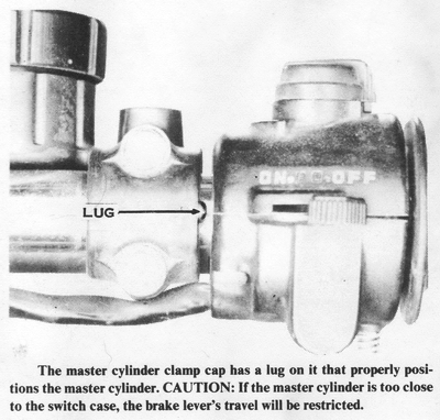
Hold the master cylinder in position on the handlebar and install the clamp cap
and bolts. The lug on the side of the clamp cap is designed to locate the master
cylinder the proper distance from the twistgrip housing. Rotate the clutch and
front brake lever brackets (and/or the master cylinder) to your preference, then
tighten the clamp bolts to 4.5 ft-Ibs. of torque. Install the mirrors.
TWISTGRIP
To remove the twistgrip, first remove the case screws. Separate the case halves
and allow them to hang by their attached wiring and cables. Turn the twistgrip
so that the cable nipple can be removed from the twistgrip reel. The cold-start
cable on 1972 models and earlier is removed in the same manner.
If the switches or wiring need to be replaced, the entire twistgrip housing must
be replaced. Remove the headlight from its shell by taking out the two screws
from the bottom of the chrome ring or out of the lower rear portion of the
shell. Unplug the headlight and put it in a safe place. CAUTION: If you allow
the headlight to hang by its wiring, it could easily pull loose and break.
These are special headlights, available only from Kawasaki dealers, and are much
more expensive than automotive-type headlights. Unplug the right-hand switch
case wiring inside the headlight shell. This includes a single black wire to the
engine stop switch on 1973 and later H1 models, and 1974 and later H2 models. To
remove the lower case half from the throttle cable (and cold-start cable on some
models), loosen the cable elbow locknut, then unscrew the elbow out of the case
half. The elbow is part of the cable housing and stays with the cable.
If you wish to replace the twistgrip rubber on 1973 and later models, you must
replace the entire reel-and-grip assembly. The plastic reel is molded into the
rubber during manufacture. If you plan to use a custom grip rubber, the old
rubber can be removed from the plastic reel by slicing it lengthwise with a
sharp knife. CAUTION: Be sure to use an adhesive designed for use with
plastic to secure the new grip rubber to the reel. If the grip rubber pulled off
during hard acceleration, you would lose control. Earlier models use a metal
reel that is a tight slip-fit into the grip rubber. NOTE: A twistgrip rubber
has a larger inside diameter than a left-hand grip rubber, to accommodate the
reel.
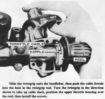
To assemble the twistgrip onto the handlebar, start by pushing the wiring
through the hole in the back of the headlight shell and securing all the items
you disconnected during removal. There should be one plastic multiprong
connector on most units and one additional black wire on 1973 and later H1
models and 1974 and later H2 models. Models from 1969 through 1972 have no
wiring to the right-hand case. but they do have a cold-start cable in addition
to the throttle cable. Insert the ends of the control cables through the
threaded holes in the lower case half. The throttle cable goes into the larger
diameter end of the case. Screw the cable elbows about halfway into the case.
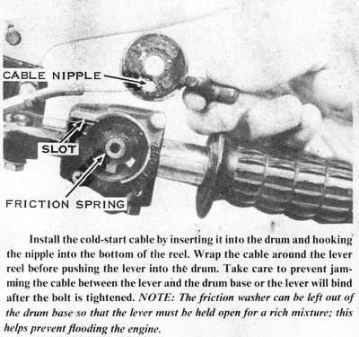
Lubricate the end of the handlebar with grease and slip the cold-start
lever-and-reel assembly onto it. Insert the cold-start and throttle cables'
nipples into the sockets on the lever-and-reel assembly. Push the end of the
cold-start lever through the slot in the lower case half, then fit the lower
case half onto the handlebars from below so that the throttle cable reel fits
into the larger diameter section of the case. Fit the upper case half and insert
the screws. CAUTION: On models with wiring to this case, be sure the wires
are not pinched during assembly. Rotate the case to position the switches.
etc., conveniently, and then tighten the screws securely. CAUTION: Remember
that the outer end of the grip rubber must not drag on the end of the handlebar.
This could stick the throttle open.
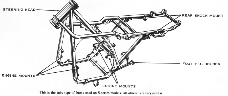
STEERING STEM
The steering stem is the kingpin of the motorcycle's frame, because it handles
the steering and front suspension forces. Both ends of the stem are supported in
the frame by uncaged ball bearings, to reduce steering friction. The bottom
triple clamp is welded to the bottom of the stem, whereas the top triple clamp
is secured to the top of the stem with a large nut or bolt. The steering fork
lock is an integral part of the bottom triple clamp or the steering head section
of the frame. On some models there is an adjustable friction-type steering
damper mounted below the bottom triple clamp to stop steering oscillations
caused by high-speed riding on uneven surfaces. It has an adjustment knob at the
top of the stem. Other models use a hydraulic-type telescopic damper between the
bottom triple clamp and the frame for the same reason. This type is adjustable
by a knob on the rear end of the damper unit. Some models have both types of
steering dampers installed at once.
CHECKING THE BEARING ADJUSTMENT
To check the steering bearings for excessive clearance, apply the front brake
and push forward on the handlebar. If the top triple clamp moves away from the
fuel tank or the steering stem clicks, the steering bearings are too loose. To
check the bearings for an excessively tight adjustment, park the motorcycle on
the center stand and sit on the seat so that the front wheel is clear of the
ground. The handlebar should fall easily from lock to lock. Tight bearings are
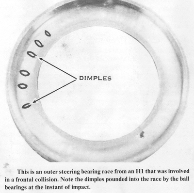
evidenced by binding or catching. NOTE: Intermittent binding of the steering
bearings indicates corrosion or cracking of the steel balls, which must be
replaced.
ADJUSTING THE BEARINGS
It is best to remove the fuel tank to gain access to the steering bearing
adjustment nut. Loosen the center clamp bolt on the top triple clamp (not found
on H1, H1A, and H1C models) and the top triple clamp stem nut or bolt. Tighten
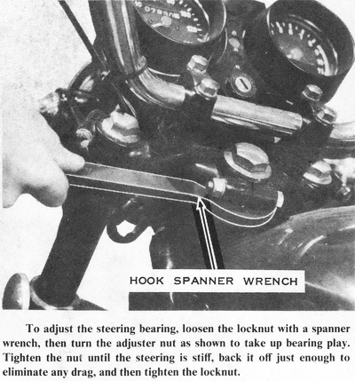
the bearing adjuster nut with a hook spanner until the steering is stiff, and
then back it off just enough to eliminate any bearing drag. Hold the adjuster
nut in this position while tightening the stem nut or bolt. Tighten the center
clamp bolt on the top triple clamp.
REMOVING
Support the motorcycle on the center stand, then take off the fuel tank and
handlebar. Remove the headlight from its shell and take off the shell from the
forks. NOTE: On some models, the shell is supported by the turn signals.
Remove the speedometer cable from the front hub, and then disconnect the brake
cable. Loosen the axle clamps or axle nut, then remove the front wheel. Remove
the front fender by taking out the bolts holding it to the fork sliders. Remove
the steering damper(s), if used. Loosen all three top triple clamp bolts, then
remove the stem nut or bolt and the fork tube top bolts (on H1, H1A, and H1C
only). Loosen the bottom triple clamp bolt on the right fork leg and the turn
signal clamp bolt, then slide the fork leg out. Store the fork leg in an upright
position, and reinsert the top bolt to keep out dust. Pull the fork cover, turn
signal clamp, and any spacers, washers, or chrome covers out from between the
top and bottom triple clamps. On disc-brake models, remove the two bolts holding
the disc brake caliper assembly to the left fork slider, and then remove the
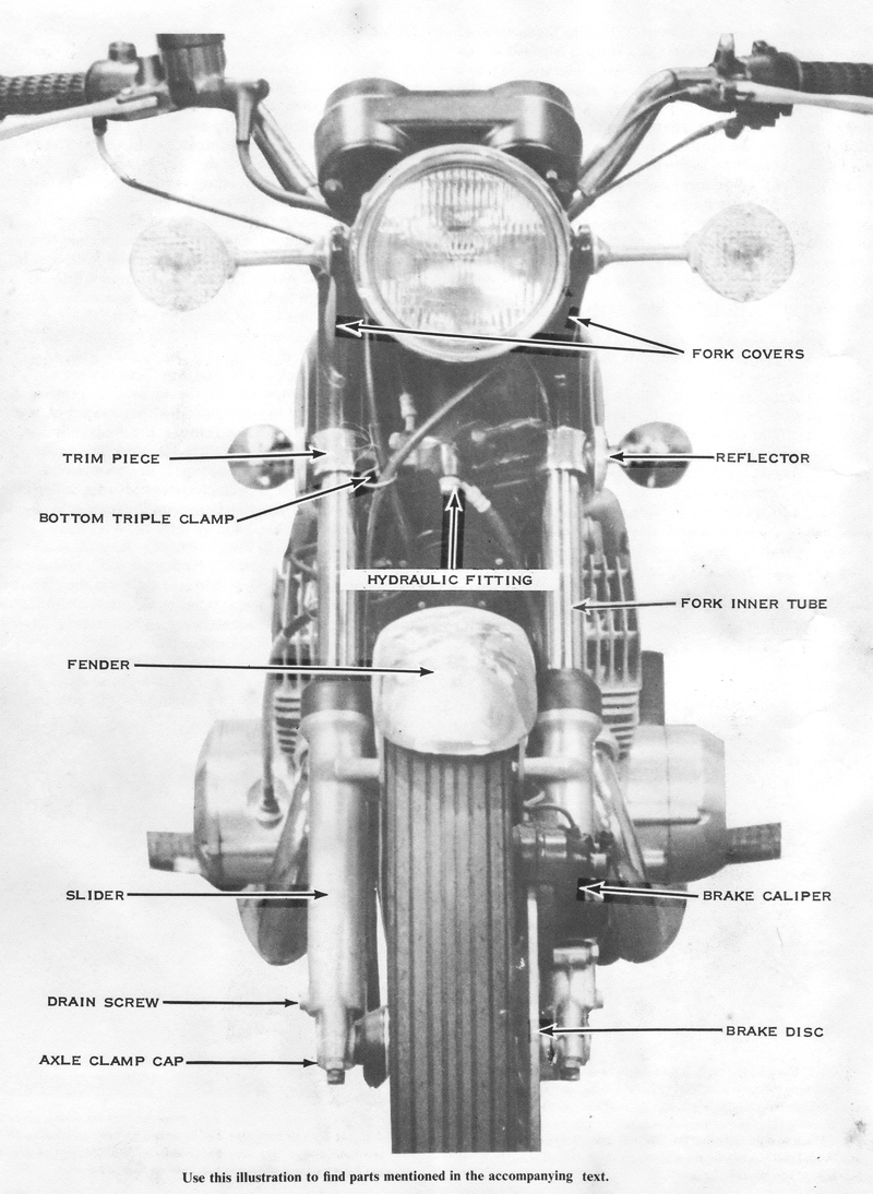
hydraulic fitting from the bottom triple clamp. Remove the entire hydraulic
system from the motorcycle in a unit to eliminate the need for bleeding the
system during assembly. NOTE: On some models, the hydraulic fitting is built
into the bottom triple clamp, and on these models the hydraulic lines must be
removed. They will need to have the hydraulic system bled during assembly.
Now loosen the bottom triple clamp bolt on the left side and slide out the left
fork leg. Pull the fork cover, turn signal clamp, and any spacers, washers, or
chrome covers out from between the top and bottom triple clamps. Remove the
speedometer and tachometer cables from the bottom of the instruments, then lift
the top triple clamp, complete with instruments, off the top of the stem. While
holding the bottom triple clamp up, remove the steering bearing adjuster nut.
Hold the top bearing race down and slowly lower the steering stem/bottom triple
clamp assembly out of the steering head so as not to lose any ball bearings.
Carefully lift the top bearing race, then remove the balls from both ends of the
stem.
CLEANING AND INSPECTING
Wash the parts in solvent and blow them off with compressed air. Wipe old grease
and dirt out of the bearing races inside the steering stem head on the frame
with a cloth soaked in solvent. Inspect the steel balls and all four bearing
races for signs of rust, wear. chips, or cracks. Replace all four of these parts
if any component is damaged. Hold a straightedge alongside the stem to check for
bending. Lay a straightedge across the two flanges on the bottom triple clamp to
make sure they are in line. Check the bores in the bottom triple clamp for signs
of fretting or uneven contact with the fork tubes. Inspect the welded joint
between the steering stem and the bottom triple clamp for signs of failure.
Check the underside of the top triple clamp for hairline cracks. NOTE. These
parts are not affected by wear as much as being susceptible to damage from the
momentary stresses resulting from a collision or accident. CAUTION:
Replace any part with questionable structure integrity. A weakened triple clamp
can separate during hard braking or cornering, and damaged steering bearings can
bind or lock up without warning.
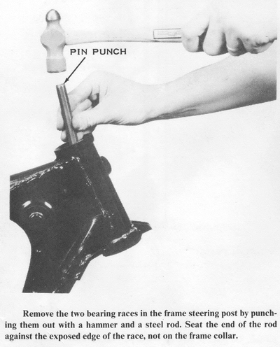
REPLACING DAMAGED BEARING RACES
To remove the two bearing races from the steering head, use a long rod and a
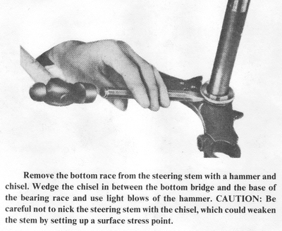
hammer to punch them out. Remove the race from the bottom of the steering stem
by inserting a chisel between the race and the bottom triple clamp. Tap the
chisel lightly all around the race to lift it free.
Install new bearing races with a hammer and a bearing driver. The bearing driver
must push against the outside edges of the steering head races and against the
inside edge of the bottom race on the steering stem. CAUTION: Make sure the
bearing races are fully seated after installation, or the steering adjustment
can loosen while riding.
INSTALLING
Use plenty of thick, waterproof grease on the steel balls and bearing races.
Install nineteen 1/4" balls in the top steering head bearing race. and nineteen
1/4" balls in the bottom steering stem race. CAUTION: Do not use more than
nineteen balls in either end of the bearing even though there seems to be room
for one more, or the steering bearings will bind. Set the topmost race on
top of the bearings in the steering head to hold them in place while carefully
lifting the steering stem into position. Put the dust cover over the top of the
stem, then thread on the adjuster nut finger tight.
Set the top triple clamp with instruments on the steering stem, but do not push
it all the way down. Insert the left-hand fork cover with the turn signal clamp
(and any spacers, washers, or chrome covers that were removed) between the top
and bottom triple clamps. Slip the left-hand fork leg into the triple clamp
assembly and snug the bottom triple clamp bolt. Fasten the hydraulic fitting to
the bottom triple clamp (or connect the hydraulic lines). Route the hydraulic
line to the master cylinder so it will go over the top triple clamp. Fasten the
caliper unit to the left fork slider and tighten the bolts to 20 ft-lbs. of
torque. Position the right-hand fork cover and turn signal clamp (with any
spacers, washers. or chrome covers that were removed) between the top and bottom
triple clamps. Slip the right fork leg into the triple clamp assembly and snug
the bottom triple clamp bolt. Install the fork tube top bolts (if they were
removed) and tighten them. Push the top triple clamp down. then install the top
stem nut or bolt. Tighten it securely. Make sure the tops of the fork tubes are
flush with the top triple clamp, and tighten all three top triple clamp bolts.
Now tighten the lower triple clamp bolts. Install the headlight and handlebars.
and then connect the wiring. Install the steering damper. if used. Be sure to
bleed the front brake hydraulic system as described later in this chapter.
FRONT FORK
The front fork supports the front of the frame and cushions it from road bumps.
Two different types of internally sprung telescopic forks are used. They are
differentiated by the fork slider material, steel or aluminum.
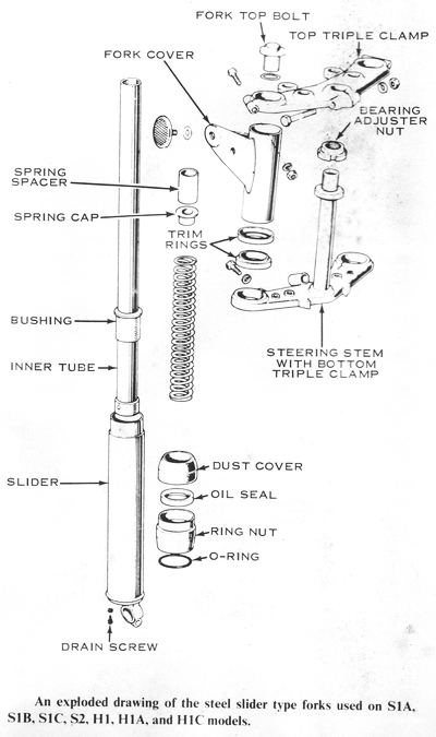
STEEL SLIDER FORKS
Steel slider forks are used on the H1, H1A, H1C, and S1 models. These also have
a drum-type front brake. The springs that support the weight of the vehicle are
inside the fork tubes. The top ends of the springs are held down by the bolts on
the top ends of the fork tubes (on the top triple clamp). The bottom ends of the
springs are pushed upward by stiff, rodlike spring holders in the centers of the
steel sliders. Each spring holder is an integral part of the slider and reaches
from the bottom of the slider to within an inch of the top. The inner tube is
chrome plated on its outer surface to make it resist the up-and-down rubbing
motion of the slider. The top end of the slider has a metal bushing inside it
that bears against the inner tube. The bottom end of the inner tube has a metal
bushing on it that bears against the inside of the slider. Thus the two tubes
(the inner tube and the slider) can telescope up and down on each other, with
the spring to hold them extended.
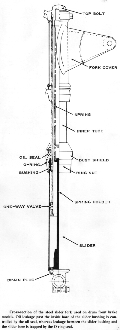
To damp the natural bouncing action of the spring, a hydraulic damping mechanism
is incorporated in the inner tube. The fork leg is full of oil which is forced
through small metering holes and one-way valves in the inner tube to control the
bounce of the spring.
DISASSEMBLING
To disassemble the fork legs, first remove the from wheel and fender. To do
this, disconnect the front brake and speedometer cables. Remove the axle cotter
pin. then unscrew the axle nut. Loosen the axle clamp boll and pull out the
axle. The wheel will drop straight down out of the forks. Remove the four bolts
holding the fender brackets to the fork sliders.
Loosen the top triple clamp bolts (S1 only), and then remove the fork top bolts.
CAUTION: These bolts hold the fork springs under compression. Hold them down
while removing them to prevent their threads being stripped. Use a strap
wrench to remove the ring nut on the top of the slider. Slip the slider down and
off the inner tube. The fork spring will come out with the slider. Pour the oil
out of the slider. Loosen the lower triple clamp bolt, then pull the inner tube
out of the triple clamps. If you remove only one side of the forks at a time,
the headlight assembly will not have to be removed.
INSPECTING
Clean the inside of the slider with solvent. The bore should be smooth, with no
scratches or worn spots. Feel the lip of the seal with your finger to check for
cuts or roughness, which indicates that replacement is necessary. Check the
piston and valve on the lower end of the inner tube. The valve plate should be
free to move up and down slightly. The outer surface of the piston should be
smooth, with no scratches or worn spots. Pull the slide bushing off the inner
tube to check its inside surface which should also be smooth, with no scratches
or worn spots. Roll the inner tube on a flat surface to check for bends or flat
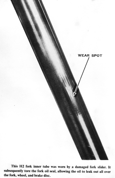
spots. Inspect the surface of the inner tube carefully for scratches, nicks,
pits, or peeling chrome, which will ruin the fork seal.
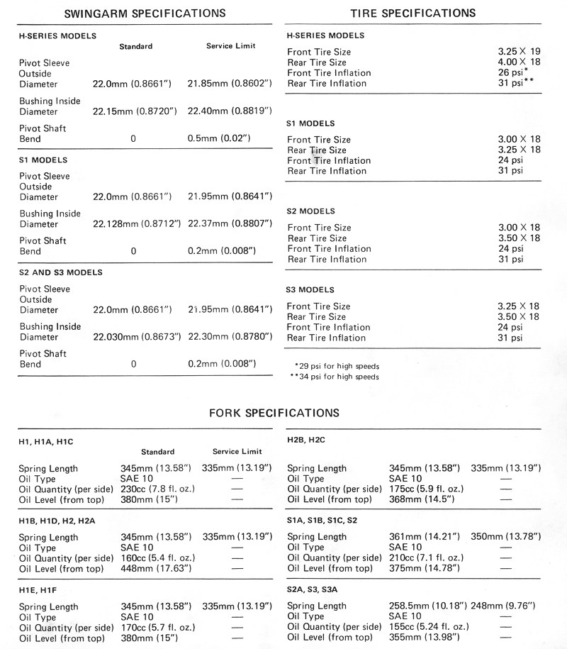
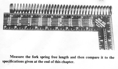
Measure the free length of the fork spring to check for weakening because of age
and use. Compare this measurement to the specification at the end of this
chapter. If it is less than the service limit, both fork springs must be
replaced to balance the spring effect in the forks.
ASSEMBLING
If you have decided to replace the fork oil seal, remove the circlip that holds
the seal into the ring nut. Pry the seal out with an appropriate tool such as a
rounded screwdriver. Carefully drive the new seal into place with a hammer,
using the old seal as a tool. The old seal will protect the new one from being
damaged by the hammer. Be sure the new seal is seated securely, then replace the
washer and circlip. Pull the O-ring out of the bottom end of the ring nut, and
then push a new one into place. NOTE: A little oil or grease on the O-ring
will make this job much easier.
Put the spring holder rod, large end first, into the slider. Oil the piston end
of the inner tube lightly with SAE 10W fork oil, then slip it into the slider so
that it fits over the end of the spring holder. Slide the metal bushing down
over the inner tube and seat it firmly to the shoulder in the slider. Slip the
ring nut on the same way and screw it securely onto the slider. Push the rubber
dust seal down over the inner tube and onto the ring nut.
Replace the fork leg in the triple clamps. and then tighten the bolts securely.
Drop the spring into the inner tube. then pour in the amount of SAE 10W fork oil
recommended in the specifications at the end of this chapter. Push the fork top
bolt down to prevent its threads from being stripped while screwing it into
place.
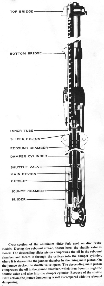
ALUMINUM SLIDER FORKS
Aluminum slider forks are used on all models from 1972 on, except the S1 models.
which use steel slider forks. The springs that support the weight of the motor
cycle are inside the upper (or inner) fork tube. The upper fork tube is a close
fit inside the aluminum slider. The top ends of the springs are held down by
bolts screwed into the upper ends of the inner fork tubes. The lower ends rest
on "fork cylinders" inside the sliders. The fork cylinders look like long rods
reaching from the bottom of the slider up into the inside of the inner tube: On
the upper end of the fork cylinder is a piston that fits the inside of the inner
fork tube. The fork spring rests on top of the piston. As the front of the
motorcycle, rises and falls. the inner tube telescopes in and out of the fork
slider. The spring holds them extended.
To resist the natural tendency of a spring to bounce, the bottom of the inner
tube has a valved piston that fits closely around the fork cylinder. Oil inside
the fork leg is forced back and forth through the valved piston, inside the fork
cylinder, and through the fork cylinder piston and into the spring chamber to
control the spring bounce. Because these parts are bathed in oil, they seldom
wear out. If the oil leaks out of the fork past the seal between the inner tube
and the slider, the loss of damping action and the oil mess will signal the
problem before any damage can occur.
DISASSEMBLING
The forks are easily disassembled if the fork seals need to be replaced. To
disassemble the fork legs, start by removing the front wheel. Take out the
speedometer cable, loosen the axle clamp cap nuts, remove the axle clamp caps,
and then drop the front wheel straight down and out of the forks. Remove the
four bolts holding the fender brackets to the fork slider and the two bolts
holding the caliper to the left-hand slider. Fashion a wire hook to hang the
caliper unit from the handlebar. If the caliper is not removed or disassembled,
the system will not need to be bled during assembly. Remove the small screw at
the bottom of each slider to drain the oil.
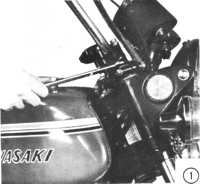
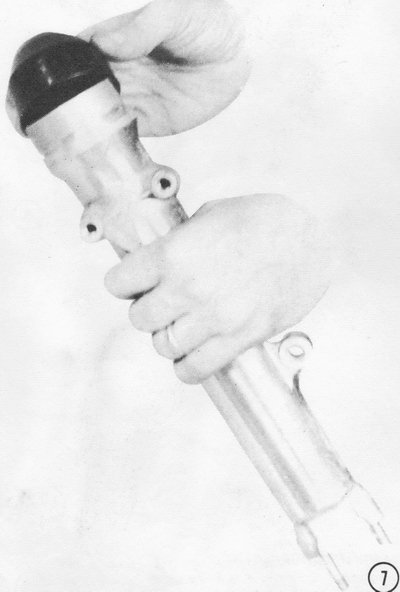
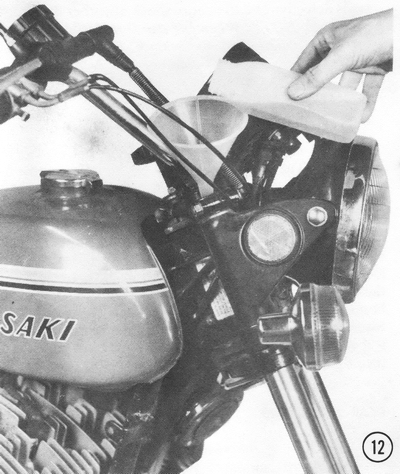
1) Loosen the top triple clamp bolts, then remove the top fork bolt as shown. Use a hooked piece of wire to pull out the fork spring and any spacers or seats. Keep them in order so you can install them correctly.
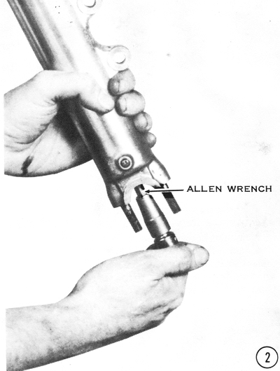
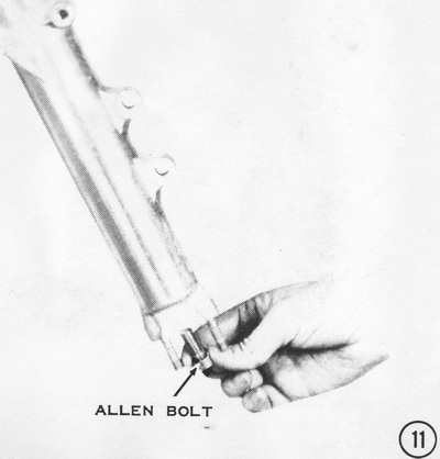
2) Use an Allen wrench to remove the bolt from the bottom of the slider. CAUTION: Do not lose the washer on this bolt. Remove the slider by pulling it straight down and off the end of the inner tube.
Note: It is sometimes easier to remove this bolt if fork is fully
assembled and a quick snap is used to break the bolt free. Use of an air gun may
be required unless a special tool is used to hold the nut within the fork leg.
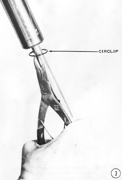
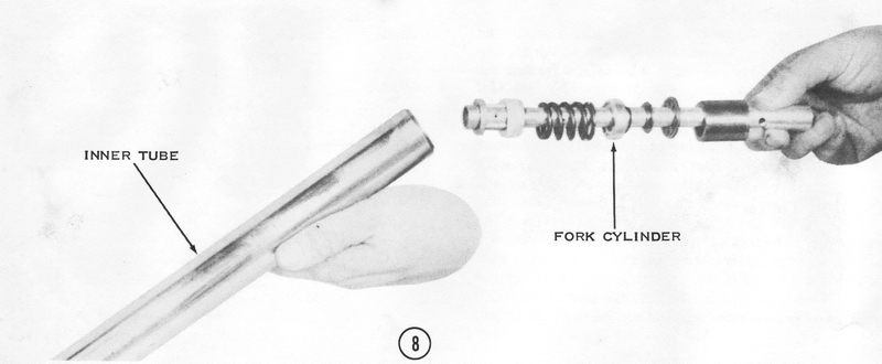
3) Use a pair of circlip pliers to remove the circlip from inside the end of the inner tube. The fork cylinder will now slide out of the inner tube. CAUTION: Do not remove the loose parts from the fork cylinder. If any of them need replacement, the entire assembly must be purchased. If there is no conical aluminum compression stop on the bottom end of the fork cylinder, it is inside the fork cylinder. Dump it out and clean the slider in solvent.
INSPECTING
Feel the lip of the seal inside the slider with your finger to check for cuts or
roughness, which indicates replacement is necessary. Look at the inner surface
of the slider with a flashlight. It should be smooth and shiny, with no
scratches or worn places; otherwise it must be replaced. Inspect the piston on
the end, of the fork cylinder. If it is scratched or shows signs of wear, the
entire fork cylinder must be replaced. The replacement cylinder will include all
of the damping mechanism parts. Wear or failure of these parts is unheard of.
Replace them only if they are obviously broken (compare them with the parts from
the other fork leg).
Loosen the lower triple clamp bolt, then remove the inner tube. Roll the tube on
a flat surface to check for bends or flattened spots, which would cause the
forks to seize. Inspect the outer surface of the tube for scratches, pits,
peeling chrome, or worn spots which would ruin the new fork seal.
The fork springs gradually weaken with use and age. Measure their free length
and compare it to the specification at the end of this chapter. If one spring is
shorter than the service limit, replace both springs to balance the front spring
force.
ASSEMBLING
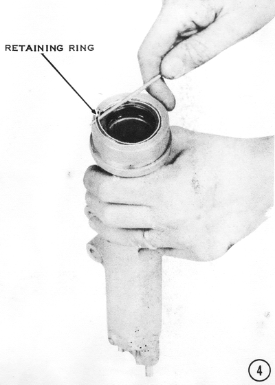
4) To replace the fork seal, first pull off the rubber dust cover, then remove
the retaining ring and washer inside the end of the slider. CAUTION: This
ring is under tension. Do not let it get away.
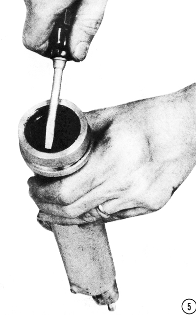
5) If the seal must be replaced, pry it out with a suitable tool such as a large screwdriver with a slightly rounded tip. CAUTION: Take care not to damage the soft aluminum slider. Use the old seal as a tool with a hammer to drive the new one into place. The old seal will protect the new one from the hammer and distribute the force of the hammer blows evenly.
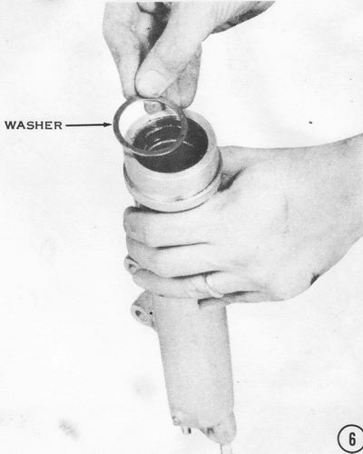
6) When the new seal is fully seated, insert the washer (shown here) and the retainer ring, which fits into a groove at the top of the slider. CAUTION: Be sure the ring fits properly into the groove. If it does not, the seal will work its way out and the fork leg will leak oil.
7) Push the rubber dust cover down over the end of the slider. Be sure it fits into the groove on the outside of the slider. NOTE: Early types of dust covers have a single taper angle. If possible, use the later types of dust covers with a double taper, they will do a much better job.
8) Insert the fork cylinder into the bottom of the inner tube. If the fork
cylinder piston has a phenolic ring around it. the cylinder can be inserted by
tipping it back and forth in the end of the inner tube while pushing it in
gently. When the cylinder fits into the inner tube, push the damping mechanism
and other assorted parts into the end of the inner tube. Refit the circlip.
CAUTION: Be sure the circlip is properly seated. If it comes out, the front
wheel can fall off the motorcycle while you are riding.
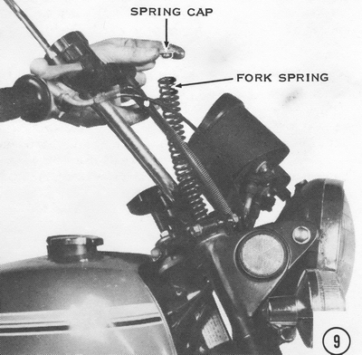
9) Put the fork spring and all spacers and spring seats into the top of the fork tube. then temporarily screw in the fork top bolt. This will hold the fork cylinder in place during the following steps.
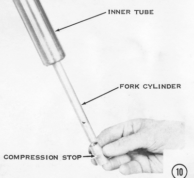
10) Slip the small conical aluminum compression stop onto the bottom of the fork
cylinder.
11) Carefully push the slider over the inner tube until you feel the fork cylinder touch the lower end of the slider. Insert the Allen bolt with its washer and tighten it securely.
12) Now remove the fork top bolt and pour in the recommended quantity of good quality SAE 10W fork oil. Check the specification tables at the end of this chapter for oil quantities and levels. CAUTION: Do not use motor oil; it will foam when the forks work back and forth and they will lose their damping action, in which case the motorcycle could become uncontrollable.
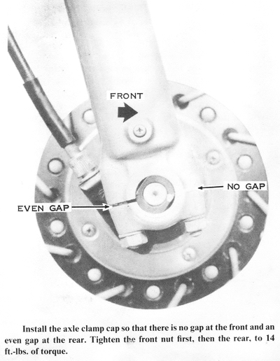
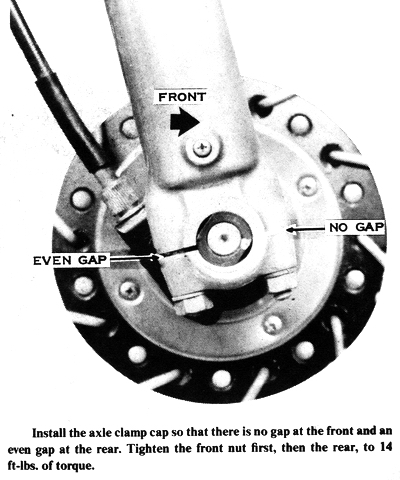
Replace the fork top bolt, then tighten it and the top triple clamp bolts securely. Remount the brake caliper, front fender, and front wheel, in that order. Torque the brake caliper mounting bolts to 20 ft-lbs. and the axle clamp nuts to 14 ft-lbs. CAUTION: Be sure the axle clamp caps mount to the end of the fork leg so there is no gap at the front and an even gap at the rear. Tighten the front nuts first, then the rear ones.
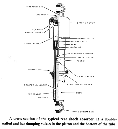
REAR SHOCK ABSORBERS
The rear shock absorbers are combined spring-damper units which support and
cushion the rear of the motorcycle frame. The top eye of each shock absorber is
mounted on the frame, whereas the bottom eye is mounted on the trailing end of
the swingarm. When the motorcycle is driven over a bump, the rear wheel lifts
the swingarm. The shock absorber springs are then compressed between the
swingarm and the rear of the frame. The hydraulic dampers resist the spring's
natural tendency to oscillate after compression, which would cause a pitching,
bouncy ride.
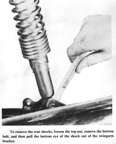
REMOVING
Support the motorcycle on the center stand. Remove the acorn nuts from the upper
shock eyes and the two bolts holding the bottom eyes to the swingarm. Push the
bottom shock eyes to the rear and out of the swingarm brackets. The rear wheel
will drop to the floor. Pull the upper ends of the shocks sideways from the
studs on the frame.
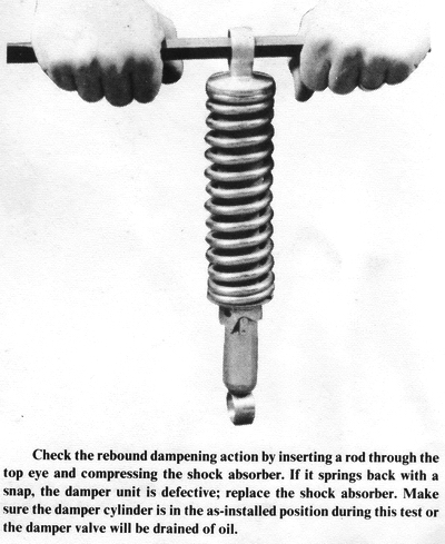
INSPECTING
To inspect the shock absorbers, hold them vertically on the floor in the same
position as on the motorcycle. Press down on the top eye as far as you can, then
release it suddenly. The shock absorber should return to its extended length
smoothly. If it returns quickly so that the bottom eye bounces off the floor,
the damping mechanism is defective and the entire shock absorber unit must be
replaced. NOTE: When one unit is replaced, the other must be replaced also to
balance the damping and springing forces on both sides of the swingarm. The
standard shocks cannot be disassembled or repaired; they are sealed units.
INSTALLING
Install new shock absorbers in pairs, as explained previously. The large tubular
end of the unit mounts to the swingarm, the other end to the frame. CAUTION:
The shock absorbers must be mounted right side up or they will not dampen
properly.
To mount the shock absorber, push the upper shock eye onto the stud on the
frame. A large flat washer, a lockwasher, and the acorn nut go on next, but do
not tighten the nut yet. Lift the rear wheel, then push the bottom shock eye
into the bracket on the swingarm. Insert the bolt with a lockwasher and tighten
it securely. Repeat the procedure with the other shock absorber, then tighten
both acorn nuts securely.
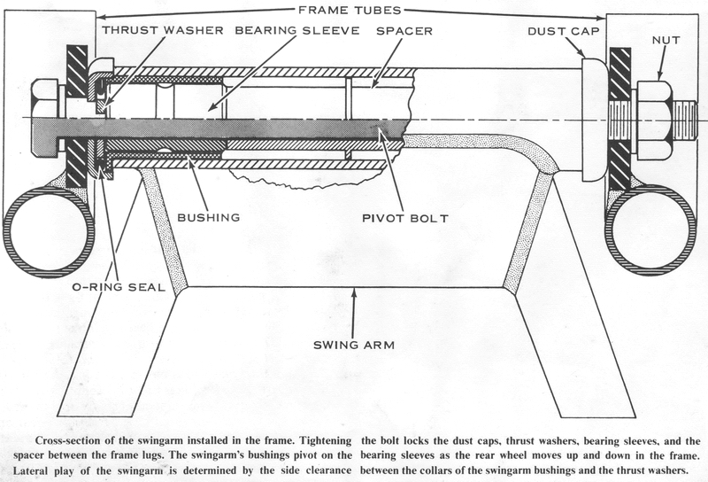
REAR SWINGARM
The front of the swingarm pivots on a large bolt which is solidly mounted
through the frame tabs just behind the engine. The up-and-down motion of the
trailing end of the swingarm and wheel is controlled by the shock absorbers,
which are fastened to the swingarm brackets and to the frame. The swingarm
performs two functions: it keeps the rear wheel aligned with the frame, and it
transmits the rear-wheel driving and braking forces to the motorcycle frame
through the pivot bolt.
LUBRICATION
The swingarm bushings should be lubricated every 2,000 miles. Loosen the
swingarm pivot bolt to provide clearance for the old grease to escape from the
bearings. Use a grease gun to force chassis-type lubricant into the grease
fitting on the swingarm pivot tube. Stop when clean lubricant flows out around
the dust covers on each end of the pivot, indicating that all the old grease has
been displaced.
INSPECTING FOR WORN BUSHINGS
Hold the rear part of the frame, then push and pull sideways on the wheel at the
top and the rear. There must not be more than 1/8" to 3/16" movement of the rear
part of the swingarm with respect to the frame. If there is excessive movement,
you must remove the swingarm and replace the bushings and sleeve bearings in the
swingarm pivot. NOTE: Worn wheel bearings will allow movement of the wheel
with respect to the swingarm. CAUTION: Make sure the swingarm is moving,
not just the wheel. The swingarm pivot bushings will wear abnormally if the
motorcycle is started and stopped abruptly or if the rear wheel is not balanced
or is out of round. Rapid wear of only the left bushing is caused by an
incorrect adjustment of the drive chain or by a badly worn chain and sprockets,
which applies alternating heavy and light forces to the left swingarm pivot
bearing.
REMOVING
Support the motorcycle on the center stand and remove the rear wheel. This will
entail removing the chain case cover and the engine sprocket on models with
endless chains (with no master link). Remove the shock absorbers. Take off the
pivot bolt nut, then slide the pivot bolt, out of the frame and swingarm. Pull
the swingarm free of the frame.
INSPECTING THE SWINGARM ALIGNMENT
Insert the pivot bolt with the sleeves and the axle (with any collars) into the
swingarm. Sight across the two shafts to see if the swingarm is bent or twisted,
which will cause the rear wheel to be cocked in the frame. Rear wheel
misalignment results in uneven tire wear, excessive chain and sprocket wear,
possible tire interference with the fender, and steering pull. Replace the
swingarm if it is damaged. NOTE: If these symptoms occur but the swingarm is
in good condition, the cause is a warped frame.
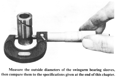
INSPECTING AND REPLACING SWINGARM BUSHINGS AND SLEEVES
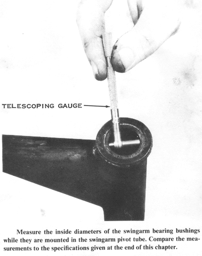
Slip the sleeves out of the bushings in the swingarm. Measure the outside
diameter of the sleeves and the inside diameter of the bushings still in the
swingarm pivot tube. Compare the measurements with the specifications at the end
of this chapter. If the outer diameter of the sleeve is smaller than the service
limit, or if the inside diameter of the bushing is larger than the service
limit, or if the surface of either the sleeve or the bushing is galled or
scored, then both the sleeves and the bushings must be replaced.
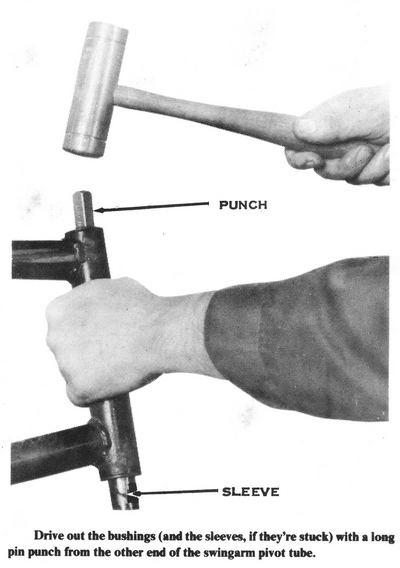
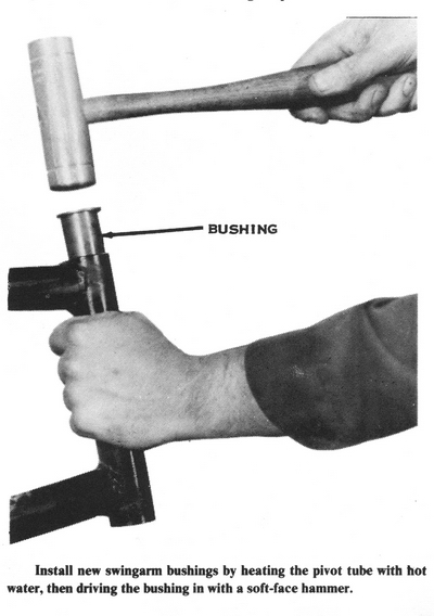
To remove the bushings, drive them out of the swingarm pivot tube with a long
pin punch and a hammer. Heat the pivot tube with boiling water to expand it
slightly, then push the new bushings into place. CAUTION: Be sure the
shoulder seats against the end of the pivot tube or the swingarm won't fit into
the frame. Grease the outside of the sleeves with chassis-type lubricant,
then slip them into the bushings with the spacer between.
To check the pivot bolt for bowing or bending, roll it along a flat surface. If the pivot bolt has a bow of more than 0.5mm (0.020") in the middle for H-series machines, or 0.2mm (0.008") for S-series machines, it must be replaced. Insert the pivot bolt into the holes in the frame lug and check for excessive clearance between the bolt shaft and the holes in the frame. NOTE: Worn frame lug holes are caused by driving with a loose swingarm pivot bolt.
INSTALLING THE SWINGARM
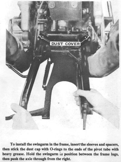
When the bushings and sleeves have been installed in the swingarm pivot tube,
liberally apply thick grease to the inside of the dust covers, then stick them
on the ends of the swingarm pivot tube. NOTE: Before installing the swingarm
in the frame on models with an endless chain, loop the chain over the swingarm
pivot tube. Hold the swingarm in place between the frame lugs, and then push
the pivot bolt into place. Install the self-locking nut with a flat washer and
tighten it to 58 to 87 ft-lbs. of torque.
Complete the installation by replacing the shock absorbers, rear wheel, and
chain, and then adjust the drive chain tension and the rear brake.
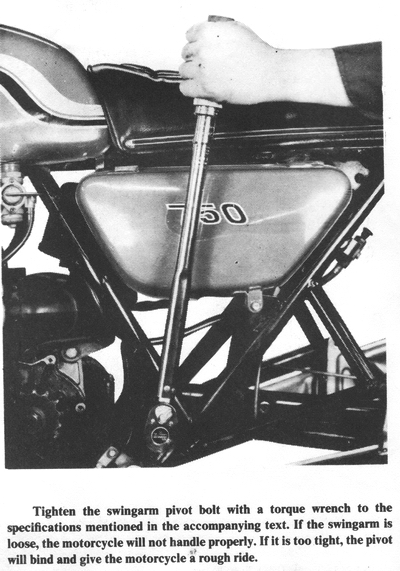
ADJUSTING THE DRIVE CHAIN TENSION
The chain should have about 5/8" to 3/4" up-and-down movement in the lower run
of chain, halfway between the sprockets, while the motorcycle is on the center
stand. Turn the rear wheel until the tightest part of the chain is at the bottom
run.
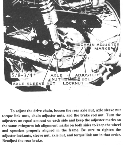
If the chain does not have the required amount of up-and-down movement, you must
move the rear axle forward (for more slack) or backward (for less slack) in the
swingarm. To adjust the drive chain tension, loosen the rear brake torque link
nuts, rear axle nut, rear axle sleeve nut (H1, H1A, H1B, and H1C only), chain
adjuster locknuts, and rear brake rod adjuster nut (H1D, H1E, and H2 models).
Turn both adjuster bolts the same amount until the chain has the correct amount
of slack. Be sure you are adjusting to the tightest part of the chain, or else
the chain will be too tight part of the time.
After adjusting the drive chain, tighten the chain adjuster locknuts, axle nut,
axle sleeve nut, torque link nuts, and brake rod nut, and then check the chain
tension again to be sure it has not changed.
LUBRICATING THE DRIVE CHAIN
The drive chain is a roller-type. As the chain goes around each of the sprockets
it must flex because each link rotates on the pins a little. A small amount of
oil between the side plates and rollers of the chain before you ride insures a
good supply of lubrication to minimize wear. Use a heavy oil such as SAE
90-weight gear oil or SAE 40 motor oil. The heavy oil sticks to the chain; a
light oil will be thrown off.
BRAKE SYSTEM
All models have internal-expanding type, mechanically-actuated,
single-leading-shoe drum brakes at the rear. The H1, H1A, H1C, S2, and all the
S1 models have an internal-expanding type, mechanically-actuated,
double-leading-shoe drum brake at the front. All other models have a
hydraulically-actuated, floating-caliper disc brake at the front. All front and
rear drum brakes are actuated by a cable, except the rear brakes on the H1D,
H1E, H1F, and H2 models, which have a tension rod. The rear brake on all models
is activated by a foot pedal on the right side of the frame, the front brake by
a hand lever on the right handlebar.
DRUM BRAKE OPERATION
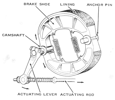
The single-leading-shoe rear brake is very simply constructed. The drum is
integral with the rear wheel hub. The open side of the drum is covered by the
brake panel, which carries two brake shoes. One end of each shoe rests on the
cam, the other on the anchor pin. When the brake pedal is depressed, the cable
or rod pulls on the actuating lever, which is fastened to the cam. As the cam is
twisted, it forces the ends of the brake shoes apart, pressing their
friction-lining-covered faces against the inside of the drum. The resulting
friction slows the rear wheel. Heavy tension springs between the shoes hold them
in place on the cam and anchor pin and retract them when the brake pedal is
released.
The single-leading-shoe brake gets its name from the fact that it has one
leading shoe and one trailing shoe. The leading shoe is the one whose leading
end is actuated by the cam. When the motorcycle is rolling forward with the
brake applied, the leading shoe supplies most of the stopping power because it
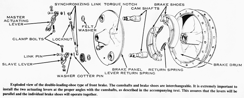
is partially self-actuated by rotation of the drum. It follows. then. that a
double-leading-shoe brake would have more stopping power for the amount of force
applied to the actuating lever because it would have two shoes instead of one
being partially self actuated by the rotation of the drum. The.
double-leading-shoe brake has two cams and two anchor pins on its panel.
arranged so that both shoes are leading shoes when the bike is moving forward.
The brake panel is locked to the motorcycle frame to prevent its twisting around
the axle with the drum when the brake is applied. The rear brake has a torque
link between the panel and the swingarm. The front brake panel has a notch in it
that engages a tongue on the inside of the left fork slider on the S2 and the S1
models and on the right fork slider on the H1 models. When the brake is applied,
the torque link is under tension. CAUTION: These torque-reaction devices must
be carefully installed and frequently inspected. If a torque link bolt falls
out, or if the panel notch is not properly meshed with the slider tongue, the
panel will twist around the axle and tear off the brake and speedometer cables.
The brake will lock up and cause skidding and loss of control, because the panel
will be pulling on the cable or rod, thereby increasing the brake shoe pressure.
DRUM BRAKE SERVICE
Drum brakes on 1974 and later models can be inspected without removing the wheel
from the motorcycle. To check brake wear, apply the brake fully and watch the
travel of the Brake Wear Indicator pointer. If it passes beyond the "Usable
Range," the brake shoes must be replaced.
To check earlier models (1969-1973) for brake wear, remove the wheel and pull
the brake panel out of the drum. Use a caliper or finely graduated scale to
measure the thickness of the brake lining material on the shoe. If it is less
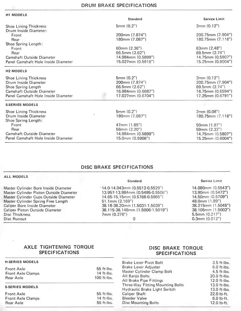
than 3mm (0.12") on the H-series models, or 2mm (0.08") on the S-series models
(at the thinnest place), the shoes must be replaced.
Measure the inside diameter of the drum and compare it to the specifications at
the end of this chapter. If the measurement is greater than the service limit,
the brake drum must be replaced.
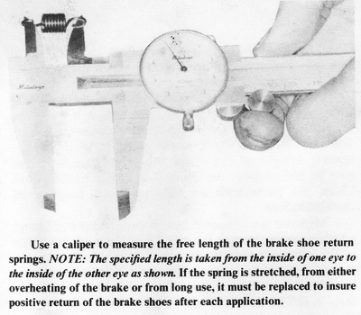
Measure the length of the brake springs and compare them with specifications. If the length of the springs is greater than the service limit, they will be too weak to retract the shoes properly and must be replaced. CAUTION: Weak springs can allow the brakes to lock unexpectedly, or not release when the pedal or lever is released.
Make aligning punch marks on the brake-actuating levers and the ends of the
camshafts. This will allow you to reinstall them in the same relative positions
during assembly. Remove the lever clamp bolts, then pull the lever(s) straight
off the camshaft(s). The camshafts can now be pulled from the inner side of the
brake panel. Clean the parts with an oilless solvent such as trichloroethylene.
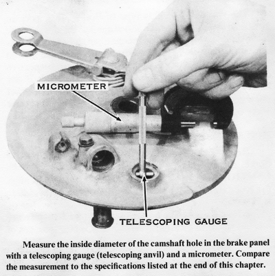
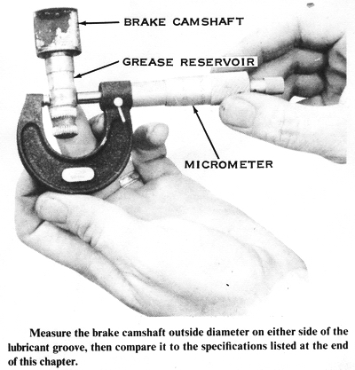
Measure the outside diameter of the brake camshaft where it passes through the
panel and the inside diameter of the camshaft hole in the panel. If the shaft
measurement is smaller than the service limit, the camshaft must be replaced. If
the camshaft hole in the panel is larger than its service limit, the panel must
be replaced. NOTE: If the panel is worn this badly, it is best to buy the
entire panel assembly, which comes complete with brake cams, shoes, and springs.
ASSEMBLING
Smear a very light film of grease on the face of the cams and a thicker coat in
the reservoir groove of the camshaft. Slip the camshaft into the hole in the
panel. From outside the panel, loop the felt dust seal over the shaft, then push
the actuating lever onto the shaft so that the punch marks align. Insert the
clamp bolts and tighten them securely.
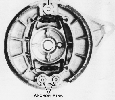
Connect the springs to the brake shoes so that when they are installed on the
panel the open hook of the spring will be toward the panel. CAUTION: If
the hook on the end of the spring is installed toward the drum, it could catch
on the rotating drum and be torn off. Now push the shoes down over the cam(s)
and anchor pin(s) until they snap into place. Wipe all excess grease from inside
the brake assembly before installing it in the drum.
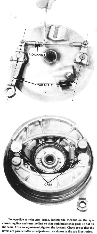
EQUALIZING A TWIN-CAM BRAKE
The two cams on this type of brake must work in unison to apply both brake shoes
against the drum at the same time. To equalize the mechanism, loosen the lock
nut on the threaded synchronizing link. Turn the link so that both brake shoe
pads lie flat on their respective cams, and then tighten the locknut.
CAUTION: If the link is incorrectly adjusted, one brake shoe will contact the
drum prematurely, causing uneven wear and erratic brake operation.
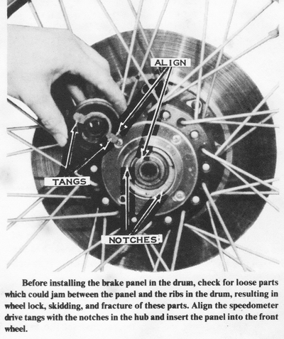
INSTALLING
Remove any loose parts inside the brake panel and brake drum, then install the
panel in the wheel. CAUTION: On front wheels, take special care to align the
speedometer drive tangs with the notched wheel hub. CAUTION: Loose parts could
jam inside the brake, which would cause the wheel hub and panel to fracture and
the wheel to lock up, resulting in skidding and loss of control.
Install the wheel on the motorcycle as described in the section of this chapter
on wheel hubs and bearings, but do not tighten the axle nut at this time. On
rear wheels, fasten the torque link to the panel by inserting the shoulder bolt
through the panel strut, turning it so that the bolt head drops into the hex
socket in the strut. Rotate the panel on the axle so the strut is at the 5
o'clock position as viewed from the right side of the motorcycle. Slip the
torque link over the bolt, then secure it with a flat washer, lockwasher, and
nut. Push the safety spring clip into the grooved section of the bolt threads.
Check to be sure the forward end of the torque link is securely fastened to the
swingarm.
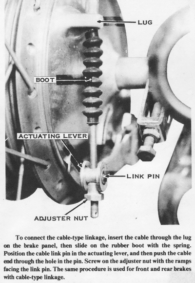
To connect the cable-type linkage, insert the cable end through the lug on the
brake panel and slip the rubber boot (with the enclosed spring) over the cable.
Position the link pin in the actuating lever, then guide the cable end through
the pin. Screw on the adjuster nut with the ramps facing the link pin. NOTE:
Check the side play of the adjuster nut in the lever ears, which must be
'I/16-3/32". Bend the lever ears to obtain the proper side play. CAUTION:
If the adjuster nut has excessive side play (caused by spreading of the lever
ears), the link pin could fall out of the lever, resulting in an inoperative
brake. NOTE: Some models have the cable end drilled to accept a cotter
pin, which must be installed at this time. Stretch the rubber boot to engage
its lip with the nipple on the cable sheath.
To connect the rod-type linkage, slide the washer and spring onto the brake rod.
and then position the link pin in the actuating lever. Push down on the brake
pedal, guide the rod through the link pin, then release the pedal. Screw on the
adjuster nut with the ramps facing the link pin. CAUTION: Don't forget to
install the washer on the brake rod before installing the spring. Otherwise, the
spring will slide up the rod, relieving tension on the adjuster nut. Vibration
and road shock could then cause the adjuster nut to slip out of the lever ears
and the link pin to fall out of the lever, rendering the brake inoperative.
Check to make sure that the forward end of the brake rod is secured to the brake
pedal and that the brake pedal is held on its pivot shaft by a washer and cotter
pin or circlip. Operate the brake pedal to check for a sticking pivot, which
could cause the rear brake to drag and the brake linings to overheat.
CENTERING THE BRAKE PANEL
It is important to center the brake panel in the drum while tightening the axle
nut. This prevents new linings from dragging on the drum and assures maximum
brake effectiveness with the shortest burnishing period. NOTE: It usually
requires 200-400 miles of use for the new brake linings to conform to a brake
drum. To center the brake panel, block up the wheel and spin it rapidly.
Apply the brake panel or lever firmly and hold it while tightening the axle nut.
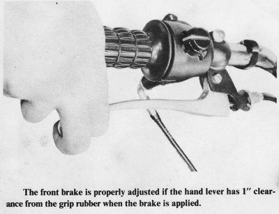
ADJUSTING THE FRONT BRAKE
If the brake lever comes closer than 1" to the handgrip when the front brake is
applied, or if you can squeeze the lever until it touches the handgrip, the
front brake must be adjusted. First loosen the locknut on the brake cable
adjuster at the brake lever. Now screw the adjuster as far into the lever
bracket as it will go, then tighten the locknut. Turn the adjuster nut on the
end of the cable at the brake panel until the brake lever has the desired amount
of free play. The front brakelight switch does not require an adjustment.
ADJUSTING THE REAR BRAKE PEDAL POSITION
Before adjusting the rear brake, first set the brake pedal's rest position. To
do this, loosen the adjuster locknut on the right side of the frame and turn the
adjuster so that the pedal rests in a comfortable position for the rider.
CAUTION: Don't position the pedal so high that your foot rests on it, or the
battery will discharge from the brake lamp being continually lit. Tighten
the locknut to secure the adjustment.
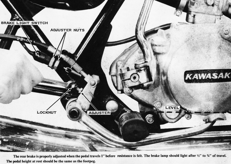
ADJUSTING THE REAR BRAKE
Turn the adjuster on the rear brake cable or rod so that the pedal travels
3/4"-1" when the brake is applied. CAUTION: Make sure there is 1/2" frame
clearance for additional pedal travel; otherwise, loss of braking could result
under hard usage. NOTE: On all models with rod-type brake linkage,
recheck the brake adjustment each time the axle is moved for taking up chain
slack.
ADJUSTING THE REAR BRAKE LIGHT SWITCH
After adjusting the rear brake, you must adjust the rear brakelight switch to be
sure that the brake lamp will light when the brake pedal has been depressed 1/2"
to 3/4". The brake lamp must light before the brake becomes effective.
To adjust the switch, loosen the two adjuster nuts on the body of the switch.
Move the switch up or down, holding it in your fingers, until the brake lamp
lights at the right time. Now turn the adjuster nuts to lock the switch into
that position. CAUTION: Overtightening the adjuster nuts can break the switch
body and short out the lighting system, which will burn out the main fuse.
When you have tightened the adjuster nuts, check the adjustment again by pushing
down on the brake pedal.
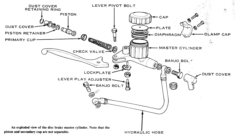
DISC BRAKE OPERATION
All disc front brakes are hydraulically operated. The master
cylinder-and-reservoir assembly is mounted on the right handlebar. The brake
disc is mounted on the left side of the wheel hub, and the single-piston
floating caliper is mounted on the left fork slider. A system of steel and
flexible brake lines connects the master cylinder to the caliper.
When the rider squeezes the brake lever, the master cylinder piston is pushed
through the cylinder, compressing the brake fluid ahead of it. The pressure of
the brake fluid is transmitted equally throughout the entire hydraulic system.
The brake lamp switch is turned on by this pressure, and the piston in the
caliper is also moved by the pressure. As the caliper piston moves out, it
forces one brake pad against the disc. The caliper slides in the other direction
until the pad on the back side also presses against the disc. The two pads pinch
the rotating disc between them and the resulting friction slows the front wheel.
The difference in size between the master cylinder piston and the caliper piston
is what gives the rider the strength to squeeze the disc hard enough to stop the
motorcycle. The area of the face of the caliper piston is about eight times as
large as the area of the master cylinder piston; this gives the rider an
eight-to-one force advantage. The brake lever is designed to give the rider an
additional five-to-one mechanical advantage over the master cylinder piston, for
a total advantage ratio of forty to one. If the rider squeezes the hand lever
with a force of 25 pounds, the pads are forced against the disc with a force of
1,000 pounds.
DISC BRAKE SERVICE
Because of the high pressures involved, hydraulic system service is very
critical. Be very careful to keep all parts as clean as possible; use only fresh
brake fluid from unopened cans marked D.O.T.3 or J-1703.
REMOVING THE PADS
When the pads have worn down to the red line on the movable pad, they must be
replaced. First the front wheel must be removed. Support the motorcycle on the
center stand. Unscrew the speedometer cable ring nut at the hub and then pull
the cable free. Remove the axle clamp cap nuts, clamp caps, and front wheel.
Remove the small screw on the wheel side of the caliper. This will allow the
fixed pad to be removed through the slot in the caliper. Now there will be room
to take out the movable pad. If it will not come out of its recess in the
caliper, squeeze the lever carefully to force it out. Remove any shims from the
back of the pad.
When the pads are both out, push the piston back into the caliper. CAUTION:
The brake fluid thereby displaced will go into the master cylinder reservoir. If
the reservoir is full, it will overflow. Do not get any brake fluid on painted
surfaces, as it will soften and stain the paint.
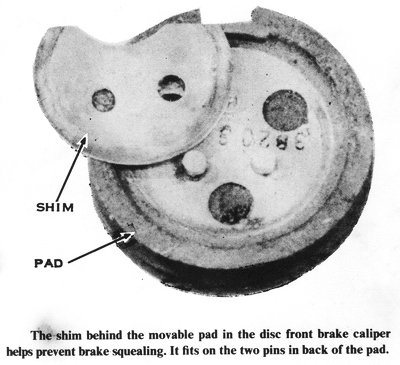
REPLACING THE PADS
If there were any shims behind the movable pad, put them onto the new one, then
insert the pad in the caliper. NOTE: The shim help stop brake squeal. Now
insert the fixed pad and tighten the screw securely.
Remount the front wheel. Remember to mount the axle clamp caps so there is no
gap at the front and an even gap at the back. Reconnect the speedometer cable,
then tighten the front two clamp nuts and then the rear nuts to 14 ft-lbs.
Pump the brake lever a few times to push the movable pad into position. Then
check that the brake fluid level is up to the line inside the reservoir.
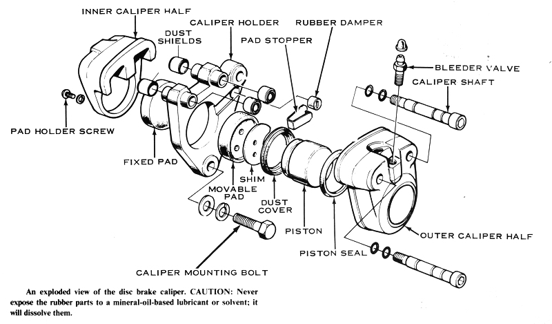
SERVICING THE CALIPER
There is no need to take off the front wheel to remove the caliper. The disc can
be inspected while the wheel is mounted.
To drain the brake fluid, push a plastic tube over the bleeder valve on the
caliper, and then put the other end into a clean container. Open the bleeder
valve, and then pump the brake lever repeatedly until no more brake fluid comes
out of the tube. Pull the tube off. and then close the bleeder valve.
Unscrew the steel tube fitting on the back of the caliper. Remove the two bolts
holding the caliper to the fork slider. Take out the small screw on the wheel
side of the caliper. This will release the stationary pad. which can be slipped
out of the slot in the caliper. The movable pad can now be removed through the
slot.
Use an Allen wrench to unscrew the caliper shafts. Pull the wheel side half of
the caliper off smoothly, taking care not to tear the 0-rings on the shafts.
Pull the shafts out of the remaining caliper half the same way. The mounting bar
will come off at this time.
The piston may not easily slide out of the caliper cylinder. If necessary, force
it out with compressed air directed into the hydraulic pipe fitting hole.
CAUTION: If high-pressure compressed air is used, the piston may be ejected
violently. Do not allow it to damage itself or anything else. Use a hooked
probe to pull the dust seal and oil seal out of the caliper bore.
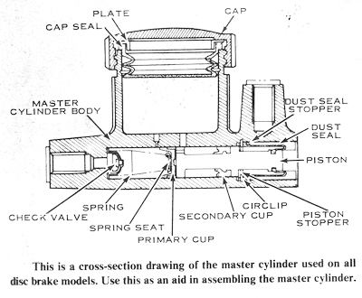
To disassemble the master cylinder, remove the banjo bolt holding the hydraulic
fitting. Unscrew the clamp bolts, then lift the master cylinder from the
handlebar.
Remove the nut on the bottom of the lever bracket, allowing the lever pivot bolt
to be withdrawn from the top. Reach into the end of the cylinder with a hooked
probe, then pull out the snap ring and the dust seal. The small inside circlip
must be removed with a pair of circlip or retaining ring pliers. NOTE: If a
tool of this type is not available, a Kawasaki special tool (part number
57001-154), can be ordered through an authorized dealer. Blow on the hose
end of the cylinder to remove the piston stopper, piston, cups, spring, and
check valve assembly. CAUTION: Do not disassemble the piston and check valve
any further. If any replacements are required, only subassemblies are available.
CLEANING AND INSPECTING
Clean all the parts of the caliper and master cylinder with clean brake fluid or
alcohol. CAUTION: If alcohol is used, do not immerse rubber parts for more
than 30 seconds, or they will be dissolved.
Inspect all the rubber parts carefully for scratches, cuts, and tears, any of
which are cause for replacement. NOTE: The rubber cup on the master cylinder
piston is not replaceable by itself. The entire piston must be replaced.
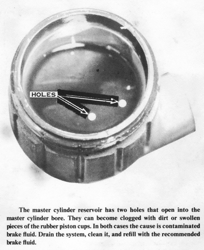
Look for scratches, shiny wear spots. rust. and pitting on the metal parts like
the two pistons and inside the master cylinder and caliper bores. Be sure the
two holes in the bottom of the reservoir are clean.
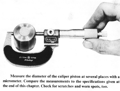
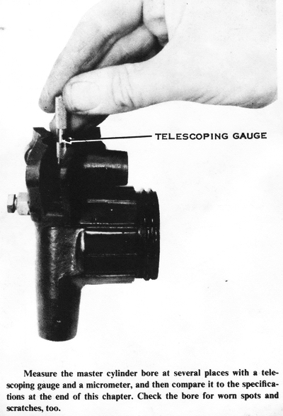
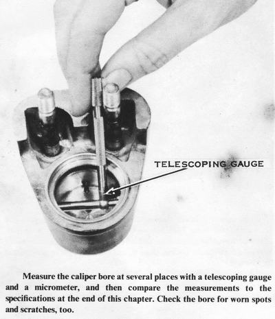
Measure the inside diameter of the caliper and master cylinder bores at several
places. If any of these dimensions are greater than the service limits at the
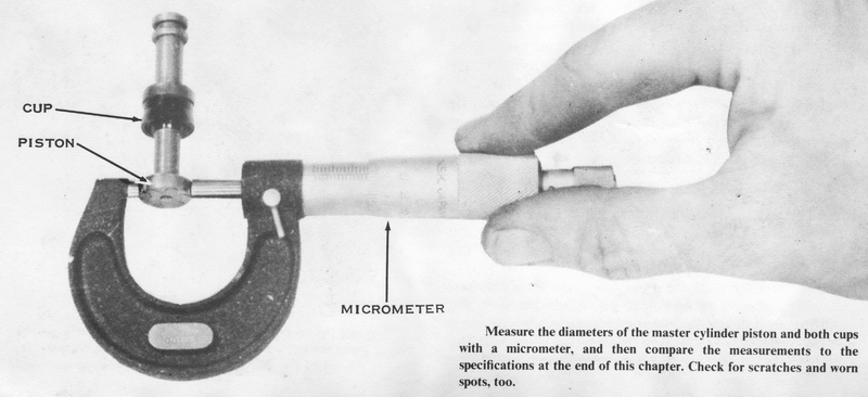
end of this chapter, the part must be replaced. Measure the outer diameter of
the caliper piston, master cylinder piston, and its two cups. If any of these
measurements are less than the service limit, the part must be replaced.
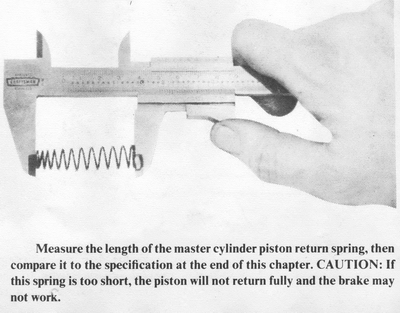
Measure the free length of the master cylinder spring. If it is less than the service limit, it must be replaced. If any of the rubber parts are swollen or lumpy, they must be replaced.
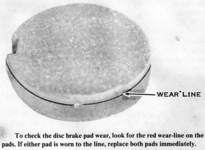
Inspect the pads for grease or dirt embedded in the friction surface. If either
pad is worn to the red line, replace both pads. Clean the pads with oilless
solvent such as trichloroethylene to remove oil or grease from the friction
material. If they will not clean up properly, replace them. NOTE: If the pads
are worn unequally, replace all the seals in the caliper and master cylinder.
The adjuster seal (caliper oil seal) may be worn out, or the relief port in the
master cylinder may be clogged by swollen pieces of a broken seal.
Bend and twist all the rubber brake hoses and look for cracks or bulges, which
indicate replacement is needed. If there are any visible leaks. replace the
affected line or gaskets (if the leak is at a fitting). The steel brake pipes
must be replaced if they are rusted, cracked, or if the plating is badly
scratched. CAUTION: This type of damage weakens the pipe and it can burst
under braking pressure, leaving you without brakes.
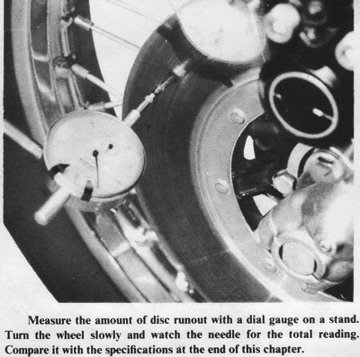
Measure the thickness of the disc at the point of most visible wear. If it is
less than 5.5mm (0.217"), the disc must be replaced. To check the disc runout.
spin the wheel with a dial gauge held against the side of the disc. If the total
indicated runout is greater than 0.3mm (0.012"), the disc must be replaced.
ASSEMBLING
If you replace the disc, it is a good idea to change the pads at the same time.
Clean the new disc thoroughly with trichloroethylene or other oilless solvent.
The disc is packaged with a rust-preventive coating which will lower the
friction coefficient of the pads if not removed completely. Replace the lock
plates under the disc mounting bolt heads, and then torque the disc bolts to 14
ft-lbs. Be sure to bend up the edges of the lock tabs to secure the
disc-mounting bolts.
To assemble the master cylinder, hold it with the bore vertical and with the
hose fitting end down. Drop the check valve in so that the rounded side is up.
Push the large end of the spring down over it. Work the primary cup (the loose
one) into the bore with the cupped side down. CAUTION: The cup must be
squeezed in. If it goes in loosely, it won't seal, and the brake won't work.
Push the piston in (after the primary cup) with the large end down. You will
have to squeeze the secondary cup as well. CAUTION: Be sure neither cup is
turned inside out or they will leak and the brake won't work. Drop the
piston stopper washer in behind the piston. Use the circlip pliers to insert the
circlip in the bottommost groove. Force the dust cap into the bore (big end
first) until the piston shows out the small end. Insert the snap ring as far
into the bore as possible to hold the dust seal in place.
Mount the master cylinder on the right handlebar with the small bump on the edge
of the clamp cap toward the right-hand switch case. This will properly space the
master cylinder from the switch case to prevent hand lever travel from being
limited by the switch case. CAUTION: If the clamp cap is installed backward,
the front brake effectiveness could be diminished. Screw in the banjo bolt
fitting and tighten it to 21 ft-lbs. of torque.
To assemble the caliper, start by pushing the square, cross-sectioned oil seal
into the caliper bore until it seats in the groove. CAUTION: The oil seal
must not be twisted in the groove or the brake will not work. Lubricate the
piston with the same brake fluid you will use to fill the system, then slip it
into the bore with the hollow side out. Snap the dust cover over the end of the
piston so that it engages the grooves in the piston and caliper.
Insert the caliper shafts through the holes in the caliper. Lubricate the four
O-rings with a little high-temperature waterproof grease, then slip them onto
the caliper shafts, one in each of the two grooves on each shaft. Push the large
end of each dust seal over the projections on the sides of the caliper-mounting
bar. Hold the caliper half in your left hand with the piston toward the right;
hold the mounting bar in your right hand with the fork mounting bolt holes
toward you and the large brake pad hole facing down. Slip the two parts together
so that the shafts go into the dust covers, through the mounting bar, and out
the dust covers on the other side. Push the shafts into the mounting bar holes
gently so that the O-rings are not damaged. Be sure the mating surfaces of the
caliper halves are absolutely clean, and then fit the halves together. Screw in
the shafts and tighten them to 24 ft-lbs. of torque. CAUTION: If the mating
surfaces are not clean, the caliper halves will not fit together properly, and
the brake may lock the wheel and cause a skid.
Fit the shim to the back of the movable pad so that it goes onto the pins. Slip
the pad between the caliper halves, then into the hole in the caliper-mounting
bar. Push it in as far as it will go. Now push the fixed pad into place in the
other caliper half, insert the screw with a lockwasher, and tighten it securely.
Mount the caliper on the fork leg so that it straddles the disc. Insert the
chrome-headed bolts with lockwashers and flat washers, then tighten them to 21
ft-lbs. of torque. Screw in the hydraulic pipe fitting, then tighten it to 12
ft-lbs. of torque. Check that all other fittings and plugs are tightened to the
torque specifications given at the end of this chapter.
BLEEDING THE HYDRAULIC SYSTEM
Fill the reservoir with extra-heavy-duty brake fluid from an unopened can marked
D.O.T.3 or J-1703. CAUTION: Disc brake fluid gets very hot in use. If you use
improper or contaminated fluid, the brake could fail. Close the bleeder
valve and attach a plastic tube to it. Immerse the other end in a container of
used brake fluid.
Pump the brake lever repeatedly until some resistance is felt. Hold the lever
against the grip, then momentarily open and close the bleeder valve. Now pump
the lever again and repeat the procedure until no more bubbles come through the
tube from the bleeder valve and the lever "feel" hardens. CAUTION: Keep the
reservoir full of brake fluid during this operation. If the level drops too far,
air will be sucked into the system, and the bleeding operation will be extended,
thus wasting fluid. If you have the double-disc accessory on your H1 or H2
model, you will have to bleed both calipers separately.
WHEEL HUBS AND BEARINGS
The front-wheel hub on drum-brake models is mounted on two ball bearings, one on
each side. A bearing spacer is used between them to support the inner races when
the axle nut is tightened. A shielded bearing is used in the open side of the
brake drum to prevent abrasive lining particles from causing premature wear and
to keep wheel-bearing grease from fouling the brake. An oil seal, axle spacer,
and dust cap are used on the opposite side of the hub to keep dirt from wearing
out the unshielded bearing.
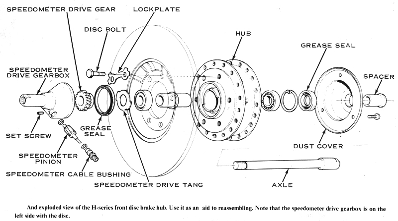
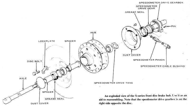
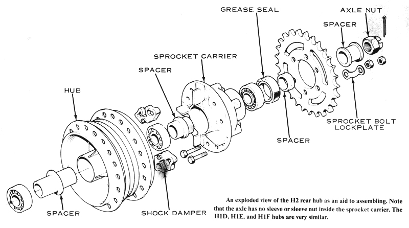
The front-wheel hub on disc brake models is mounted on two ball bearings, one on each side. A bearing spacer is used between them to support the inner races when the axle shaft is tightened. The H-series models have an oil seal, a spacer, and a dust cover on the right side of the hub, and an oil seal and the speedometer drive gearbox on the left side to keep the lubricant in the bearings. The S-series models have an oil seal and the speedometer drive gearbox on the right side of the hub, and an oil seal. a spacer, and a dust cover on the left. This is because the center of the smaller diameter S-series disc is not large enough to allow the speedometer drive gearbox to be mounted inside it.
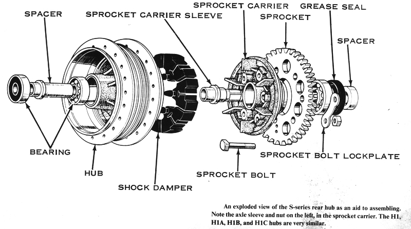
A two-piece hub is used on the rear wheel. The sprocket is mounted on a carrier
that drives the hub through four rubber torque shock dampers. The wheel hub is
supported on the axle by two bearings with a spacer. The sprocket carrier has
its own bearing, which is mounted on an axle sleeve in S-series, H1, H1A, H1B,
and H1C models, and on the axle in all other models. The separate axle sleeve is
fastened to the left side of the swingarm by a large nut with a flat washer,
allowing removal of the rear wheel hub without disturbing the chain. The
intermeshed metal vanes of the wheel hub and sprocket carrier are separated by
the torque shock absorber rubber segments. When an abrupt drive or coast loading
is transmitted through the torque shock absorber, the rubber segments are
crushed between the vanes, and this reduces chain and spoke stresses.
REMOVING
Take off the wheel. On models so equipped, remove the sprocket carrier by
loosening the large nut on the axle sleeve and then lifting the carrier from the
swingarm. Pry out the oil seal from the hub, then use a broad blunt punch to
drive the wheel bearings out of the hub. To remove the first bearing, insert the
punch through the inner race of the opposite bearing. Tilt the spacer inside the
hub and position the end of the punch against the bearing.
To remove the front disc brake hub bearings, remove the front wheel, then
unscrew the axle using a pair of 19mm open-end wrenches. Remove the dust cover,
spacer, and speedometer drive gearbox. The disc need not be removed to drive out
the bearings as described above, but be careful not to damage the disc.
CLEANING AND INSPECTING
Wash the bearings by soaking them in a mesh basket suspended in a container of
clean petroleum solvent or kerosene. Allow them to soak for at least six hours
to soften hard deposits. Use a stiff, clean brush to remove all foreign
material, rinsing the bearing after each brushing. Dry the bearings with
filtered, dry, compressed air. CAUTION: Don't spin the bearings with the
compressed air or they will be damaged from insufficient lubrication or dirt.
NOTE: The sealed or shielded bearings require repeated washing to insure
satisfactory removal of all contaminants.
Hold the inner race and slowly turn the outer race in both directions to check
for chipped balls or damaged races. Replace any wheel bearing that has more than
0.020" side play or noticeable radial play. If a bearing is determined to be
usable, immerse it in 10W oil and rotate it to displace entrapped solvent.
CAUTION: To prevent rust from attacking the precision-finished parts of the
bearing, keep the interval from cleaning to lubrication as short as possible.
If the bearing is not to be installed immediately, coat it with a
rust-inhibiting oil and wrap it in clean oilproof paper.
Clean the inside of the hub with a cloth soaked in solvent, taking care not to
contaminate the brake drum surface. Inspect the outer races of the bearings and
the hub's bearing bores for signs of fretting or bearing creep. If there is
evidence of movement between the bearing outer races and the hub, replace these
parts. Check for wear between the bearing inner races and the axle.
Roll the axle on a flat surface to check for bending. Replace the axle if it is
more than 0.020" out of true. If the oil seal lips are cut, worn, or hardened,
replace the seal.
Check the torque shock absorber segments for eroding, tearing, or hardening.
NOTE: A damaged torque shock absorber segment is evidenced by noise or lurching
when accelerating from a stop, the result o f excessive clearance between the
absorber segments and the vanes in the hub and sprocket carrier.
ASSEMBLING
Smear high-temperature, water-insoluble grease between the races of the bearings
and inside the wheel hub. CAUTION: Don't get any grease on the brake drum or
brake shoes. Clean all grit or particles from the bearing bores in the hub,
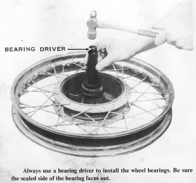
then use a bearing driver to install the bearing in the open side of the brake
drum, taking care to position it with the shielded side facing out. Turn the
wheel over and insert the bearing spacer. Install the bearing with a bearing
driver, taking care to position it with the shielded side facing out.
Make sure the bearings' outer races are fully seated against the ridges in the
hub bore by checking for a gap between the inner race and the bearing spacer. If
there is a gap, one of the bearings is not seated properly, the spacer is too
short, or it has been crushed by overtightening. NOTE: If the wheel bearings
are improperly seated, there will be a gap between the brake panel and the wheel
hub, and it will be difficult to slide the wheel assembly between the
fork-sliders or swingarm tabs. Also, the bearings will be subjected to excessive
side loadings when the axle nut is tightened. CAUTION: A crushed or short
bearing spacer could cause the brake drum flange to rub against the brake panel
rim, resulting in scorching of these parts and excessive drag.
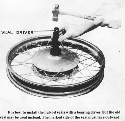
Install the bearing in the sprocket carrier from the outside with a bearing
driver. Lubricate the outside edge of the oil seal, then use a seal driver to
install it next to the bearing, with the marked side facing out.
Grease the lips of the oil seal, insert the axle sleeve into the bearing, and
push the left spacer over the sleeve and into the seal, taking care not to
distort the outer lip. Position the left chain adjuster (with the large holes)
over the left swingarm tab. Turn the axle sleeve (on models so equipped) so that
its flats align with the slot in the swingarm tab, and then push it through the
chain adjuster and swingarm. Install the axle sleeve nut, but do not tighten it
at this time. Connect the drive chain. On models without an axle sleeve inside
the sprocket carrier, the short spacer fits into the oil seal from the inside.
The torque shock absorber segments have little nipples that fit into holes in
the back of the wheel hub. Push the segments into place in the hub. The wheel is
now ready for mounting.
INSTALLING THE WHEELS
To assemble the drum brake front wheel for mounting, insert the axle spacer
through the seal lips, then position the dust cap over the spacer. NOTE: To
prevent squeaking, smear grease inside the seal and dust cap. Install the
brake panel in the hub, taking care to line up the speedometer drive tangs.
Position the large axle spacer next to the brake panel, then hold the wheel
between the forks while installing the axle.
To assemble the disc brake front wheel for mounting, grease the lips of the oil
seal and attach the dust cover with four screws. Push the axle through the dust
cover. Slip the speedometer drive gearbox onto the axle, taking care to align
the speedometer drive tangs with the notches in the hub. Screw in the axle and
torque it to 55 ft-lbs. Hold the wheel between the forks, with the disc in the
caliper and the ends of the axle between the studs on the bottoms of the fork
sliders. Install the axle caps so there is no gap at the front and an even gap
at the back. Tighten the nuts to 14 ft-lbs. of torque, first the front nuts and
then the rear ones.
To install the two-piece rear wheel with the axle sleeve, slide the sleeve into
the sprocket carrier. Hold the left chain adjuster (with the two large holes)
over the left swingarm tab, and then insert the axle sleeve through them,
turning it to line up the sleeve's flats with the swingarm slot. Thread on the
large nut, but do not tighten it at this time. Position the wheel hub (with the
brake panel installed) next to the carrier. Position the right chain adjuster on
the swingarm tab, and hold the large spacer beside it. Slide the axle through
from the right side, and then install the castellated nut. Connect the chain,
adjust the slack; and then tighten the axle.
To install the two-piece rear wheel without the axle sleeve, slide the sprocket
carrier into the wheel hub (meshing the carrier vanes with the torque shock
absorber rubber segments). Fit the brake panel into the drum. Hold the chain
adjuster over the axle hole in the right swingarm tab, push the axle partway
through, and then slip the spacer over the axle. Hold the wheel assembly up
between the swingarm tabs, and then push the axle almost all the way through.
Position the chain adjuster over the axle hole in the left swingarm tab, and
then push the axle the rest of the way through. Install the castellated nut with
a flat washer. Tighten the nut according to the torque specifications given at
the end of this chapter.
TIRES AND TUBES
The motorcycle's tires are extremely important for safe cornering, braking, and
accelerating. The conventional pavement tire has a tread contact area less than
half the size of the palm of your hand.
These models are equipped with two different types of tires, for front and rear
wheels. The front tire has a narrow cross-section and a ribbed-tread pattern,
which resists sideslip during cornering and offers reduced rolling friction. The
rear tire has a wider cross-section and incorporates a traction-block pattern
for good grip during acceleration and braking.
INFLATION PRESSURE
Refer to the specification table for the correct inflation pressures for the
front and rear tires of your motorcycle. CAUTION: To maintain safe handling,
the inflation pressures must be increased when a passenger or additional weight
is carried. Incorrect inflation pressures lead to uneven tire wear,
deterioration of riding quality, and unpredictable handling; therefore. always
use an accurate pressure gauge when inflating the tires.
REMOVING A TIRE
Take off the wheel and lay it on a smooth surface with the brake drum facing
down. CAUTION: Spread a blanket underneath the wheel to prevent scratching
the hub, disc, or rim. Use chalk to mark the tire sidewall in line with the
valve stem so that the tire can be matched to the rim during assembly.
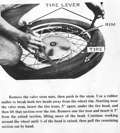
Deflate the innertube by unscrewing the valve cap, reversing it, and then using
the slotted end to remove the valve core. CAUTION: Cup your hand over the
valve stem to prevent losing the valve core when it flies out. Remove the
nuts from the valve stem, then push the stem inside the rim. NOTE: The valve
stem base in the innertube clamps the tire beads to the rim; it will be
impossible to break the tire bead from the rim without first loosening the valve
stem nuts. Loosen and push in any tire bead clamps.
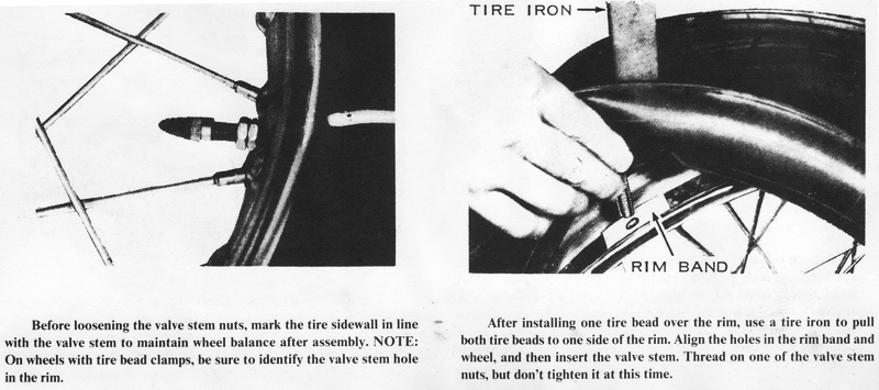
Use a rubber mallet to break the tire beads away from both sides of the wheel
rim. Starting near the valve stem, insert two tire irons, about 5" apart,
between the tire bead and the rim. At the same time, kneel on the tire just
opposite the valve stem to force the tire bead into the "dropped" center of the
rim. Pry the bead up over the rim and slide one iron toward the other to
disengage the rim from the bead. Insert this tire iron 3" away from the raised
section, then lift the bead over the rim. CAUTION: Insert the tire iron only
as much as is necessary to pick up the tire bead, or you will pinch the
innertube. CAUTION: Don't use any sharp-edged tools, or you will damage the tire
bead.
Reach inside the tire and curl out the valve stem, then pull out the rest of the
innertube. NOTE: It isn't necessary to remove the tire from the wheel rim if
you only want to repair or replace the innertube. To remove the tire from
the rim, lift the bead and take out any tire bead clamps. Push one side of the
remaining bead into the "dropped" center of the rim and use the tire irons to
lift the bead over the rim. Remove the rim band by stretching it over the rim.
INSPECTING
Check the spokes to make sure none protrudes from its nipple. Remove the nipple
from any protruding spoke, then file the spoke end so it will be 3/32" shy of
protruding. CAUTION: If the spoke is left flush with the nipple, it could
puncture the innertube after subsequent tightening.
Check the inside surface of the wheel rim for rust, rough welds, or burrs which
could cut the innertube. Use a file and emery cloth to remove any defects, and
spray the area with enamel. Check the inside surface of the tire for punctures,
cracks, or metal particles which could pinch or cut the tube. A thin patch can
be used to cover a minor defect in the tire lining.
Repair the innertube if the puncture is less than 3/8" long. Replace the
innertube if the puncture is larger or if the base of the valve stem is torn.
NOTE: Such damage results from running with low tire pressure, a loose
valve-stem nut, or a loose tire-bead clamp, because the tire has slipped on the
rim during hard acceleration or braking, carrying the innertube around with it.
INSTALLING
Stretch the rim band over the wheel and position the valve stem hole over the
matching hole in the rim. Make sure the rim band is the correct diameter and
width for your motorcycle. If it is too narrow or small, some of the spoke
nipples could contact the innertube to cause a flat tire. If it is too wide or
large, it may overlap and interfere with the innertube.
Sprinkle talcum powder inside the tire to reduce friction with the innertube.
Brush a soapy solution onto the tire beads, then pry one bead over the rim.
NOTE: Most new tires can be installed either way, but used tires have
established a wear pattern which dictates installation in the same direction
they had been used. Reversing a used tire can prolong its life slightly, but
it may result in erratic handling until the tread wear evens itself. CAUTION:
If a tire has an arrow on the sidewall, it indicates the direction of the
motorcycle when the arrow is at the top of the tire, directly above the axle.
Such a tire must be mounted this way on H-series models to prevent its being
torn apart by the power of the engine.
Pry down both tire beads until the valve stem hole is exposed, and insert the
valve stem through the rim band and the wheel rim. Thread the nut on three
turns, but don't tighten it at this time. NOTE: Install the tire bead clamp(s),
if used, in the same manner.
Tuck the innertube inside the tire, taking care not to twist it. Before
installing the remaining tire bead, temporarily inflate the innertube to align
it inside the tire. Push out the valve stem and any tire bead clamps from the
wheel center, then fit the remaining tire bead by hand, starting at a point
opposite the valve stem. Use tire irons to pry the last third of the bead over
the rim. CAUTION: Don't trap the clamping part of the innertube between the
bead and the rim or you will pinch the tube.
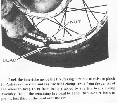
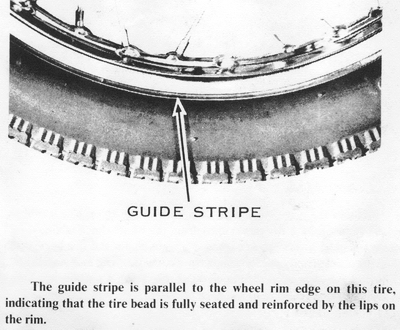
Shift the tire on the rim until the valve stem points directly to the center of
the wheel. CAUTION: If the tire is inflated with the valve stem cocked, the
innertube will tear. To maintain wheel balance, line up the chalk mark on
the tire's sidewall with the valve stem. NOTE: Some replacement tires have a
dot or other mark on the sidewall to identify the lightest sector of the tire.
This dot should be aligned with the valve stem and the bead clamp.
Use the valve cap to install the valve core, then inflate the tire to twice
normal pressure. Rock the valve stem from side to side to release air trapped
between the innertube and tire. Check for even bead seating on the rim by
checking the guide stripe on the tire, which must be parallel with the wheel rim
edge. Use soapy water on the rim edge, then strike the tire's sidewall glancing
blows with a rubber mallet to pull the tire bead out against the rim. NOTE:
When properly installed, the tire's sidewall will be reinforced by the wheel
rim. If the tire bead is not fully seated, the tire loses this lateral support
and becomes too flexible. CAUTION: If the motorcycle is driven with a
half seated tire, high-speed cornering and straight-line stability could be
adversely affected. This is especially true of poorly seated rear tires.
Deflate the tire to the recommended pressure, tighten the valve stem nut, and
then secure it with the locknut. Install the valve cap. Tighten the nuts and
lock nuts on any tire bead clamps. Install the wheel on the motorcycle.
CAUTION: If a new tire is installed, allow 200 miles of careful driving until
the tread wears in. New tire treads are comparatively smooth and slick from
the molding process, and they lack the normal traction and cornering
characteristics of used tires.
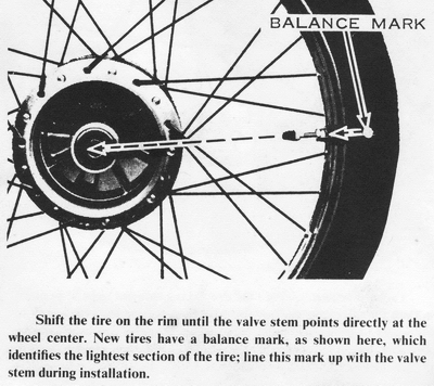 WHEEL BALANCING
Wheel imbalance can cause wheel hop and pounding vibrations at speeds over 65
mph. As long as the original-equipment tires are used, wheel balance can be
maintained by taking care to remount a tire in its original position. When a new
tire or wheel rim is installed, or when the original tire has been installed
haphazardly, the wheel must be rebalanced.
The wheels can be balanced without removing them from the motorcycle. Back off
the brake cable adjustment so there is no drag on the brake drum. At the rear
wheel. separate the chain and remove it from the sprocket. At the front wheel,
detach the speedometer drive cable. Remove all factory wheel weights.
Park the motorcycle on the center stand so the wheel spins freely. Give the
wheel a slight spin and let it stop of its own accord. Mark the wheel at the
bottom and spin it again. If the wheel stops at the same position (mark at the
bottom), it is out of balance.
Different size lead weights (10 gr. and 20 ar.) are available for balancing
wheels. These are slotted to fit over a spoke, then must be clamped around the
spoke nipple with a pair of pliers. As an alternative, you can wrap a length of
solder around the spoke just above the nipple for balancing weight. At a point
on the rim directly opposite the heavy mark make another mark and spin the wheel
again. Increase the size of the weights until the wheel stops with the light
mark at the bottom. Move the weights three or four spokes from the light mark
and recheck the balance. When the wheel stops at random positions during three
or four spins, it is properly balanced. NOTE: The purpose of using two
weights and spreading them apart is to triangulate the weight concentrations
around the wheel rim, rather than having two opposing heavy sectors acting on
the wheel rim, spokes, and wheel hub spoke flange. Install the drive chain
or the speedometer cable and adjust the brake.