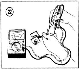
 1. Measure
resistance between each yellow lead and the red lead (Figure 22). Record
each ohmmeter reading.
1. Measure
resistance between each yellow lead and the red lead (Figure 22). Record
each ohmmeter reading.RECTIFIER
The rectifier assembly serves two purposes. It converts alternating current produced by the alternator into direct current, which is used to charge the battery. It also prevents discharge of the battery through the alternator when the engine isn’t running, or at other times when the output voltage of the alternator is less than battery voltage.
KH250, KH400, and S Series Rectifier Troubleshooting
The rectifier assembly has 3 yellow leads, one red lead and one black lead.
1. Measure
resistance between each yellow lead and the red lead (Figure 22). Record
each ohmmeter reading.
2. Reverse the ohmmeter leads and repeat Step 1.
3. If each pair of measurements was essentially infinite in one direction and low in the reverse direction, proceed with Step 4. If any pair of measurements was either high or low in both directions, replace the rectifier assembly.
4. Measure resistance between each yellow lead and the black lead. Record the meter readings.
5. Reverse the meter connections and repeat Step 4. If any pair of measurements was either high or low in both directions, replace the rectifier assembly.
KH500 and H1 Rectifier Troubleshooting
The HI rectifier is similar to that for S series models, except that it has one additional blue lead to be checked. Proceed as follows:
1. Measure resistance between each yellow wire to the red wire. Record the meter indications.
2. Reverse the meter leads and repeat the measurements.
3. If each pair of measurements was essentially infinite in one direction and low in the reverse direction, proceed with Step 4. If any pair of measurements was either high or low in both directions, replace the rectifier.
4. Measure the resistance between each yellow wire and the black wire. Record the meter indications.
5. Reverse the meter leads and repeat the measurements. If any pair of measurements was either high or low in both directions, replace the rectifier. If OK, proceed with Step 6.
6. Measure resistance between the black and blue wires, then reverse the meter leads and repeat the measurement. If the meter indicates low resistance in one direction and high resistance with the leads reversed, the rectifier is OK. If both measurements are either high or low, replace the rectifier.
H2 Voltage Regulator/Rectifier Troubleshooting
Note: Also see http://kawatriple.com/bulletins/73-h9.pdf
|
Regulator |
 The
H2 rectifier unit performs the dual functions of current rectification and
voltage regulation. To check the unit, proceed as follows:
The
H2 rectifier unit performs the dual functions of current rectification and
voltage regulation. To check the unit, proceed as follows:
|
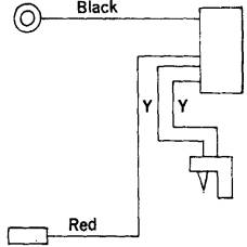
2. Measure resistance between the black lead and each yellow lead, then repeat the measurements with the meter leads reversed. Resistance should be approximately 25 ohms in one direction and 1,000 ohms in the other.
|
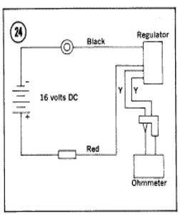
 4.
Connect the circuit shown in Figure
24 using a suitable power supply.
Then measure resistance between the two yellow leads. Resistance should be
essentially infinite in one direction and approximately 500 ohms with the
ohmmeter leads reversed.
4.
Connect the circuit shown in Figure
24 using a suitable power supply.
Then measure resistance between the two yellow leads. Resistance should be
essentially infinite in one direction and approximately 500 ohms with the
ohmmeter leads reversed.
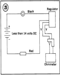
5. Reverse the power supply polarity, and lower its output voltage, as shown in Figure 25. Measure resistance between both yellow leads. Resistance should be essentially infinite in both directions.
6. Replace the rectifier unit if it fails any of the foregoing tests.